
This two-part blog series explores crucial factors influencing the optimal position of beam hangers, with a focus on gravity loading, fire safety, and seismic drift. Part 1 explores ideal placements and discusses the heightened prying effect at beam-to-column joints under seismic loading. Part 2 provides solutions to meet increased deformational demands during seismic events, accommodating designs with and without stringent fire protection requirements.
Approximately a 6-minute read
In modern mass timber structures, beam-to-column connections, often established with beam hangers, are pivotal for distributing loads. For design guidance with these pre-engineered connectors, refer to our Beam Hangers Design Guide. Three key factors—gravity loading, fire safety, and seismic drift—significantly influence the ideal position of beam hangers, as illustrated in the simplified model in Figure 1.
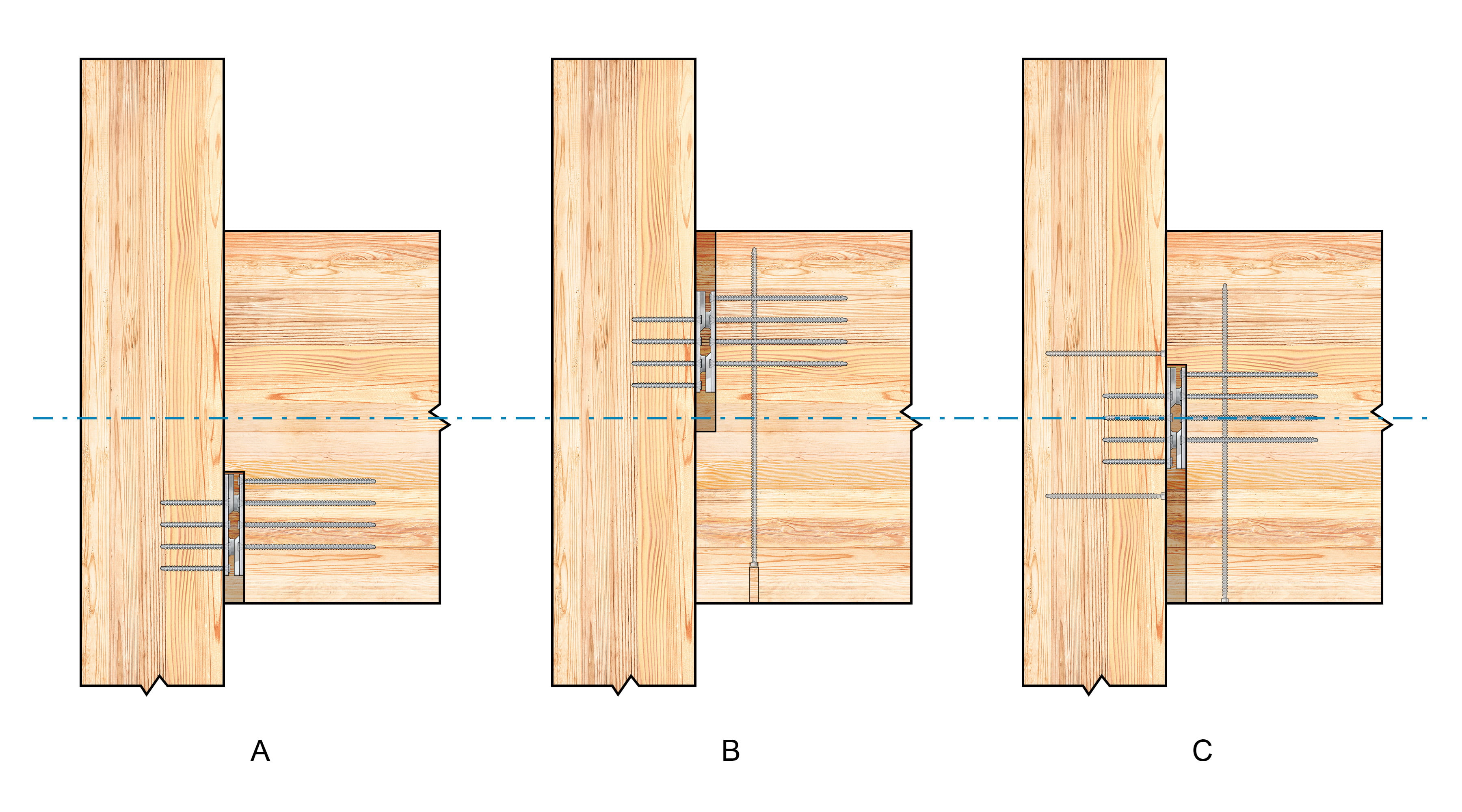
Figure 1. Ideal beam-hanger placements considering (A) gravity loading, (B) fire safety, and (C) seismic drift
Gravity Loading
To address gravity loading, it is imperative to position the beam hanger as low as possible on the beam end (Figure 1A), adhering to the so-called “70% rule” detailed in our white paper, Supplementary Considerations for the Conventional Yield Model. This placement minimizes the risk of wood splitting, ensuring a robust assembly. However, this gravity consideration should be balanced with the prescribed geometry requirements, as outlined in our blog post series, Geometry Requirements for Structural Screws [Part 1] and [Part 2].
Fire Safety
In taller mass timber buildings, fire safety emerges as a paramount concern. Regulatory mandates for adequate wood cover at beam-to-column connections necessitate a higher beam-hanger placement to accommodate the required sacrificial layer. Should this requirement conflict with the 70% rule, it is advisable to insert reinforcing screws perpendicular to the grain near potential points of crack initiation in the beam. Shielding these screws from fire exposure requires countersinking them into the timber, which can be achieved by drilling a borehole before installation and sealing it afterward with a wood plug (Figure 1B). The depth of the borehole depends on the specific fire-resistance rating requirements. Of note, the connector installation sequence demands attention in this scenario.
Seismic Drift
In earthquake-prone regions, installing the beam hanger on the neutral axis of the section, accounting for any anticipated contribution from the panels above to the prying effect at the beam-to-column joint, is essential to minimize induced deformation at the connection during seismic events. Any departure from this position or neglecting contributions from boundary conditions, such as those introduced by the gap at the beam-to-column joint, brings the beam hanger closer to the area of extreme deformation at the top or bottom edge of the section, thereby increasing the stress at the connection. Contributions from localized stiffness and associated effects at the beam-to-column joint should also be taken into account. The overall stiffness of the beam-to-column joint is influenced by the stiffness of the panel-to-beam connection.
Ensuring optimal connection performance under seismic loading requires a holistic consideration of additional factors, notably gravity loading and tensile demands in the column. Deviations from the 70% rule related to gravity loading can be similarly addressed with perpendicular-to-grain reinforcing screws in the beam. The induced drift introduces tension components and tensile stresses within the fasteners embedded in the column, resulting in a higher risk of splitting. Prevention calls for the incorporation of additional perpendicular-to-grain reinforcing screws in the column (Figure 1C). Moreover, if fire safety is a vital concern, the approach presented earlier to protect the reinforcing screws should also be implemented.
Increased Load Demands Under Imposed Drift
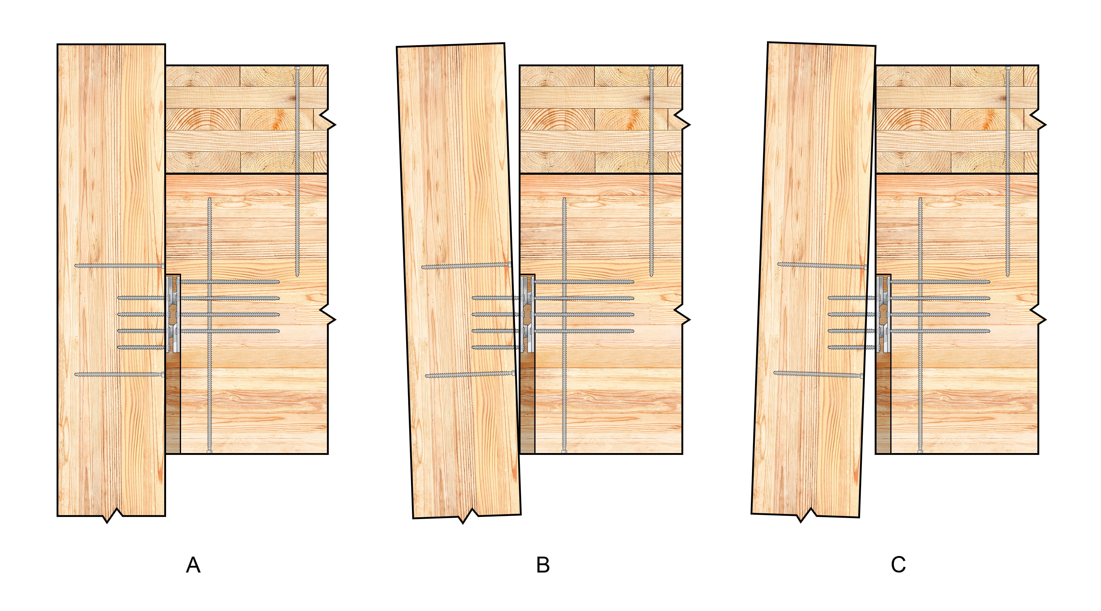
Figure 2. Impact of seismic drift on tension at a beam-to-column joint
In real-world applications, beams are often used to support floors composed of cross-laminated timber (CLT) panels. Typically, a CLT floor assembly is secured to the underlying beams using screws, which may introduce varying degrees of stiffness and composite action along the panel-to-beam joint, depending on the detail employed.
As explained earlier, the key to minimizing deformation at the connection during seismic events lies in positioning the beam hanger at the neutral axis of the section. Determining the location of this axis necessitates the consideration of the contribution from the CLT panel above the beam. The presence of this panel shifts the effective idealized center of rotation, potentially intensifying the prying effect on the connector and jeopardizing its structural performance and integrity under imposed drift.
A simplified model of a CLT floor assembly with a beam-to-column connection is used for explanation (Figure 2A). In this model, the beam hanger is placed on the neutral axis of the beam, without considering the presence of the CLT panel. It is important to note that these considerations do not yet explicitly account for contributions at the joint itself.
Seismic loading causes the column to sway left and right. During leftward motion, the CLT panel has minimal impact on the stress at the connection due to the absence of a direct load path (Figure 2B). Conversely, during rightward motion, the CLT panel bears against the face of the column, forming a direct load path that extends the lever arm. As a result, even a small overall deformation can yield a relatively substantial prying effect at the connection (Figure 2C). This heightened prying effect increases the tension at the connection assembly, potentially leading to a range of undesirable outcomes. These may include wood cracking in the column, fastener withdrawal from both the column and the beam, and increased damage to the beam hanger.
Optimizing beam-hanger position involves an evaluation of various factors, primarily from gravity, fire, and seismic perspectives. Part 2 of this series further explores challenges posed by seismic events and presents practical approaches to address them. For more information and design guidance, please contact our Technical Support Team. 🙂
Register for a Technical Learning Session
Sign up for MTC Newsletter and keep up to date with all our progress.