
This two-part blog series explores crucial factors influencing the optimal position of beam hangers, with a focus on gravity loading, fire safety, and seismic drift. Part 1 explores ideal placements and discusses the heightened prying effect at beam-to-column joints under seismic loading. Part 2 provides solutions to meet increased deformational demands during seismic events, accommodating designs with and without stringent fire protection requirements.
Approximately a 6-minute read
Stress Reduction Solutions with the Consideration of Fire Safety
Continuing from Part 1 of this series, Part 2 presents two solutions to alleviate the forces at beam-to-column connections anticipated during seismic events. While such demands are largely dictated by the framing specifications and other system-level factors, provisions can be implemented at the beam–column interface to improve drift performance by isolating the contributing elements and introducing additional sources of flexibility, as illustrated in Figure 1.
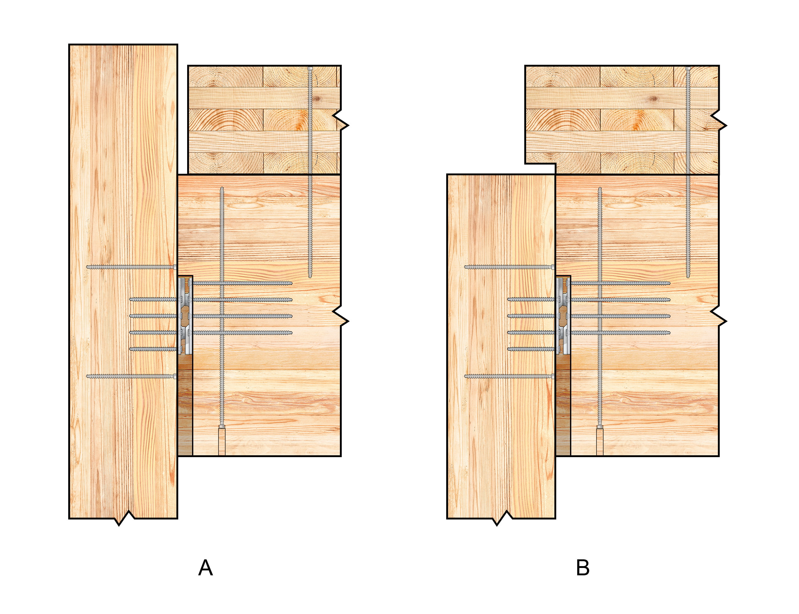
Figure 1. Stress reduction solutions considering fire protection
As discussed in Part 1, the stress at the connection is influenced by the presence of a direct load path at the beam–column interface. Therefore, both remedial solutions revolve around partially isolating or eliminating this load path.
The first approach involves widening the gap between the narrow edge of the cross-laminated timber (CLT) panel and the face of the column. The increased spacing effectively prevents bearing at this interface, thereby eliminating the direct contribution of the panel to joint stiffness (Figure 1A). The gap should be sized adequately to fully isolate the panel at the maximum imposed drift, accounting for the gap dimension and center of rotation at the joint.
Alternatively, the column can be terminated flush with the top face of the beam, permitting the CLT panel to extend over the column (Figure 1B). Crucially, it is imperative to detail a notch at the bottom of the panel directly above the column and avoid a direct load path between these two members. These measures further isolate the panel from the column as it sways during a seismic event.
While these provisions are effective at relieving stresses developed at the beam-to-column joint, designers are advised to carefully assess other structural considerations that could significantly contribute to the overall burden on the connector. The recommendation given in Part 1 to install reinforcing screws perpendicular to the grain in the column holds, especially in situations where the potential risk of splitting is deemed unacceptable. This risk becomes more pronounced in scenarios where the fasteners in the connector are near the column end or splice joint, such as the one illustrated in Figure 1B.
Stress Reduction Solutions without the Consideration of Fire Safety
Another strategy is available to mitigate drift-induced stresses at beam-to-column connections, particularly for buildings or sections without a mandated design requirement for fire protection.
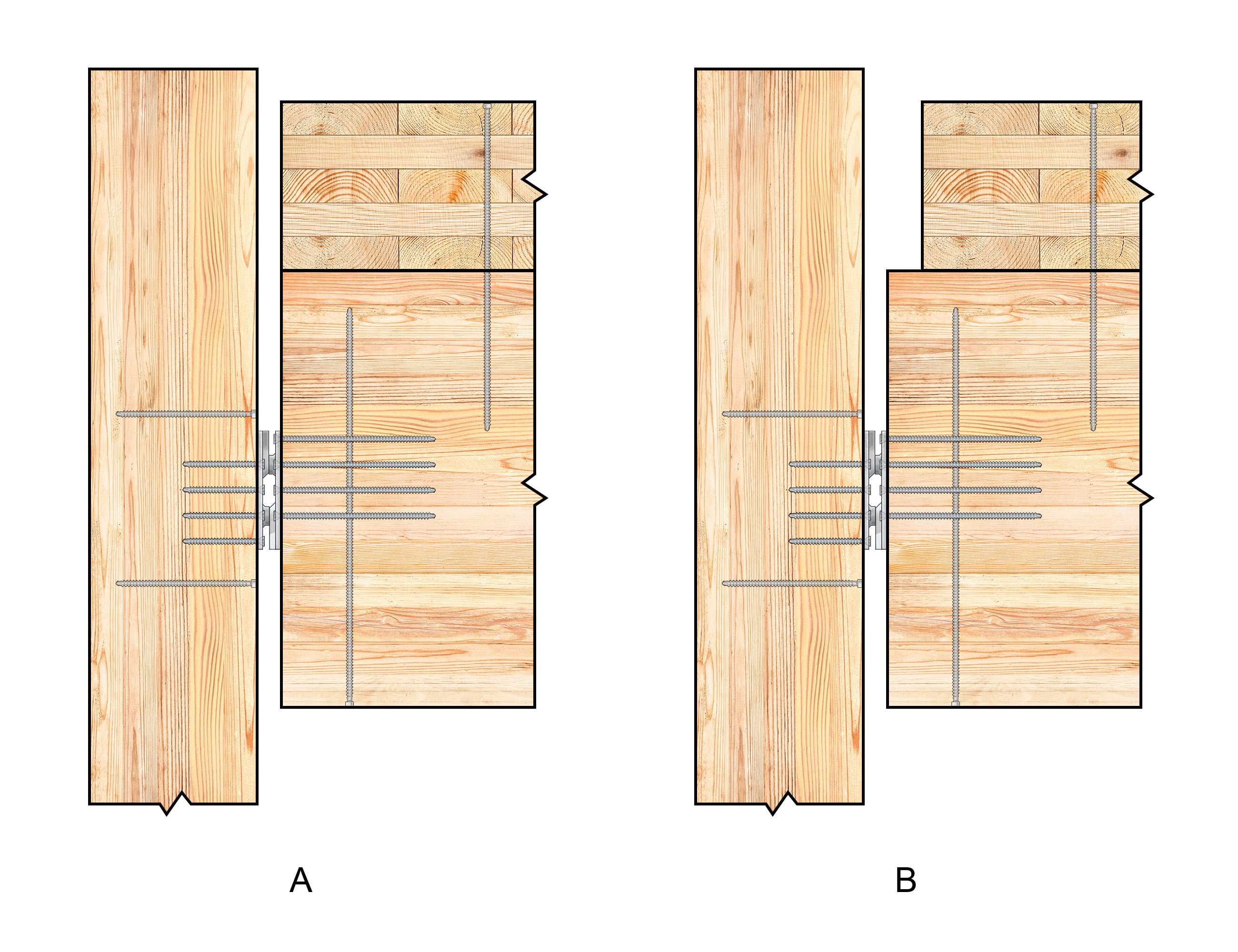
Figure 2. Stress reduction solutions without stringent fire safety considerations
While effective, the solutions presented above do not address the prying effect of the beam as it bears against the column during seismic events. Additionally, their effectiveness is constrained by the framing depth and other system considerations.
In instances where fire protection requirements permit an exposed connector or do not necessitate a bonded joint, widening the interface gap between the beam and the column becomes a viable approach (Figure 2A). This extended gap can substantially delay the formation of a direct load path between the beam and the column while reducing stresses arising from imposed drift. Overall, this isolation of the connector influences rotational joint stiffness and moderates joint behavior, meriting consideration during the design phase.
When the connector is fully exposed, the gap size equals its thickness (assuming the absence of a housing or cut-end detailing), which may not be sufficient to completely prevent bearing at the joint under significant drift demands. Similar bearing may occur at less significant drift demands in cases where a smaller interface gap is justified to meet fire protection requirements. In both scenarios, the response will transition to behaviors discussed in Part 1 when the imposed drift is significant enough to close the gap and induce bearing at the interface.
Importantly, before this interface gap closes, the position of the connector will not influence the joint stiffness or stresses developed; rather, it will dictate the rotation of the joint at which bearing occurs. In such cases, the connector alone bears the gravity load and rotational demands, essentially acting as a soft hinge, while the gap remains present. Careful detailing is therefore warranted to ensure the structural integrity of the assembly under seismic loading. Reinforcement should be implemented as required to reduce the risk of wood splitting.
Higher seismic risks and other design considerations may require a larger gap between the CLT panel and the column, as shown in Figure 2B. This measure echoes the principle shown in Figure 1A.
Various measures are available to minimize drift-induced stresses at beam-to-column connections, and the choice among them hinges on the significance of fire protection as a design concern. Refer to Part 1 for ideal beam-hanger positions considering gravity loading, fire safety, and seismic drift and our Beam Hangers Design Guide for design guidance with beam hangers. For more information, contact our Technical Support Team.🙂
Register for a Technical Learning Session
Sign up for MTC Newsletter and keep up to date with all our progress.