

Concealed connection systems are often selected for mass timber projects where the wood is both a structural element and an architectural feature. Architects and designers often take advantage of the natural beauty of timber by leaving the wood exposed while concealing structural connections within the member. Rather than encasing structural members in fireproofing materials such as gypsum board, exposed timber construction relies on the inherent fire performance of the wood itself. As a result, fire protection for concealed connection systems can be achieved by maintaining adequate wood cover around the connection.
This blog post provides an overview of the calculation methods and detailing considerations used to achieve fire-rated concealed post-to-beam and beam-to-girder connections using MTC Solutions’ pre-engineered Beam Hanger Systems.
It focuses specifically on protecting concealed connection components from fire exposure. The fire design of the timber members themselves, including determination of the sacrificial wood layer and verification that the remaining effective cross section satisfies the applicable structural requirements, is outside the scope of this article and must be completed by the Engineer of Record.
Approximately 10-minute reading time.
Fire Design Principles
Fire-rated design of concealed connections begins with understanding how timber responds to fire and how the remaining wood protects embedded structural components.
Charring
Heavy timber elements have long been recognized for their excellent performance in fire due to charring. During a fire event, a layer of char forms on the exposed wood surfaces, creating an insulating barrier that slows heat penetration and further charring. Because this char layer develops in a predictable manner, timber members can be designed with sacrificial wood that is expected to char during a fire while the remaining section continues to support structural loads.
For concealed connections, this same mechanism also protects embedded structural components. Sufficient wood cover must remain between the connection and the fire-exposed surfaces throughout the required fire-resistance period.
Protection of Concealed Connections
The fire performance of concealed connections relies on more than just the visible char layer. As wood is exposed to elevated temperatures, a region beneath the char layer undergoes thermal degradation before becoming fully charred. This region, commonly referred to as the pyrolysis zone, experiences a reduction in strength and stiffness as the wood is progressively heated. Although this region remains visually intact, its reduced mechanical properties must still be considered during fire design because the effects of fire extend deeper than the visible char line alone.
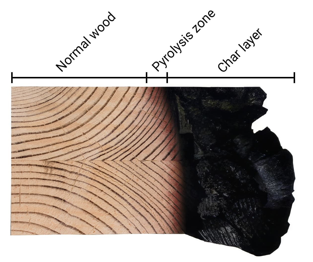
Figure 1. Char layer and pyrolysis zone in fire-exposed timber
For concealed connections, the surrounding timber therefore acts as a protective envelope that shields embedded components from direct fire exposure and excessive temperatures. Maintaining adequate wood cover around the connection allows the system to achieve the desired fire-resistance rating.
Timber charring is a non-linear process because the char layer acts as an insulator, slowing the rate of combustion as it develops. A constant linear char rate does not fully capture this changing behaviour, underpredicting char depth at shorter fire exposures and overpredicting char depth at longer fire exposures.
Understanding these fire design principles provides the foundation for the calculation methods used to design fire-rated concealed connections. In practice, the objective of these methods is to ensure that all concealed structural components remain within this protected region throughout the required fire-resistance period.
Calculation-Based Design
Calculation-based approaches can be used to determine the protection required for concealed connections to achieve a specified fire-resistance rating. While the applicable design standards differ between Canada and the United States, the approaches share many of the same underlying fire design principles and technical guidance. The applicable design standards and supporting technical guidance for each jurisdiction are summarized in Figure 2.
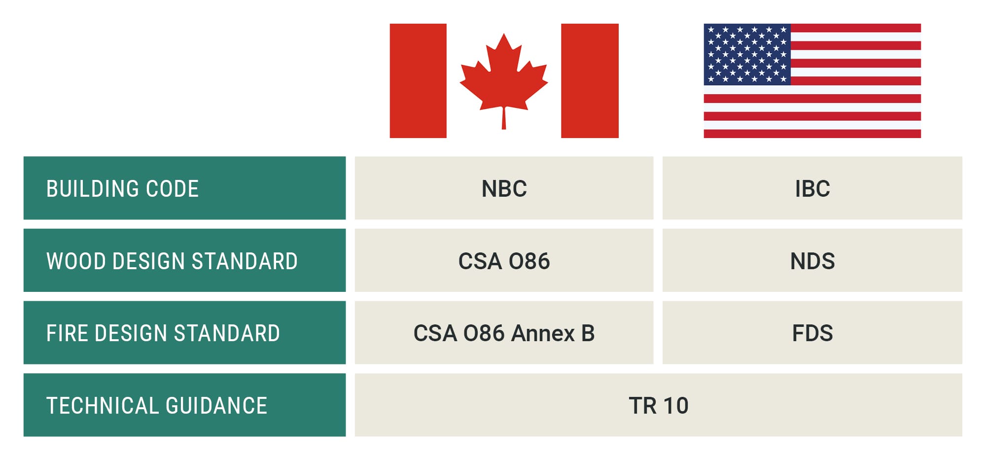
Figure 2. Canadian and US design frameworks for calculation-based design
Canadian Design: CSA O86
In Canada, fire design of timber structures is addressed by CSA O86. Annex B includes provisions relevant to the fire design of concealed connections and references AWC Technical Report No. 10 (TR10) for additional guidance on timber fire design.
CSA O86 Annex B provides two approaches for calculating char depth. The one-dimensional method uses a nominal char rate, β₀, of 0.65 mm/min and accounts for a prescribed zero-strength layer and corner rounding. The notional method uses a notional char rate, βₙ, of 0.70 mm/min and produces a simplified rectangular residual section without explicitly accounting for corner rounding, which is explained later in this article. For concealed connection protection, the one-dimensional method provides a more direct representation of the fire-affected geometry surrounding the connection.
For fire exposures greater than 20 minutes, the effective char depth for the one-dimensional method is calculated as:
𝑎𝑒𝑓𝑓 = 0.65𝑡 + 7mm
where 𝑡 is the fire exposure duration in minutes and 𝑎𝑒𝑓𝑓 is the effective char depth required in mm.
At two hours of fire exposure, this results in an effective char depth of 3-11/32 in. [85 mm].
US Design: FDS and Technical Report No. 10
In the United States, fire design provisions for wood construction are provided through the National Design Specification (NDS) and AWC Fire Design Specification (FDS). The FDS includes provisions for the fire design of wood members, assemblies, and connections, including calculation methods for protection provided by wood cover.
AWC Technical Report No. 10 (TR10) provides additional technical guidance and design examples supporting these methods. Unlike a constant linear char-rate approach, the TR10 methodology accounts for the non-linear progression of charring with time. For concealed connections, the required protection depth, 𝑑𝑝, is calculated as:
𝑑𝑝 = 1.5(𝐹𝑅𝑅/0.85)0.813
where 𝐹𝑅𝑅 is the required fire-resistance rating in hours and 𝑑𝑝 is the required protection depth in inches.
For example, for a 2-hour fire-resistance rating, the TR10 methodology results in a required protection depth of approximately 3.0 in. [76 mm].
Connection Protection Considerations
Determining the required protection depth is only one part of designing a fire-rated concealed connection. The geometry and detailing of the connection must also ensure that sufficient timber remains between the concealed components and the fire-exposed surfaces throughout the required fire-resistance period.
Effective Cross Section
The effective cross section represents the portion of the timber member that retains its structural properties during a fire event and can therefore be relied upon to resist structural loads. For concealed connections, the calculated fire-affected geometry is also used to evaluate whether sufficient timber remains between the concealed connection components and the fire-exposed surfaces. The required protection depth can then be used to establish the minimum member geometry needed to maintain the connector within this protected region.
The geometry of the effective cross section depends on the calculation method used. CSA O86 provides two linear approaches: the one-dimensional method, which accounts for corner rounding, discussed shortly, and the notional method, which produces a simplified rectangular residual section. TR10 instead uses a non-linear charring model to determine the char depth and required protection depth.
Corner Rounding Effect
During a fire event, timber members are often exposed to fire on multiple faces, resulting in greater charring at corners than on adjacent flat surfaces. Since standard charring equations assume one-dimensional heat transfer, they do not fully capture this effect.
CSA O86 accounts for this additional material loss through corner rounding, with the corner rounding radius taken equal to the calculated char depth. For concealed connections located near the bottom corners of a member, this can place portions of the connector within the fire-affected region even when the calculated char depth is provided as nominal side and bottom cover.
The connection must therefore be positioned to remain within the effective cross section after corner rounding is considered. This may require additional side cover, additional bottom cover, or a combination of both.
Increasing the bottom cover may require the connector to be positioned higher within the member. When doing so, other structural requirements, including perpendicular-to-grain splitting, must also be considered. For MTC beam hangers, the applicable connector positioning requirements are provided in the Beam Hanger Design Guide.
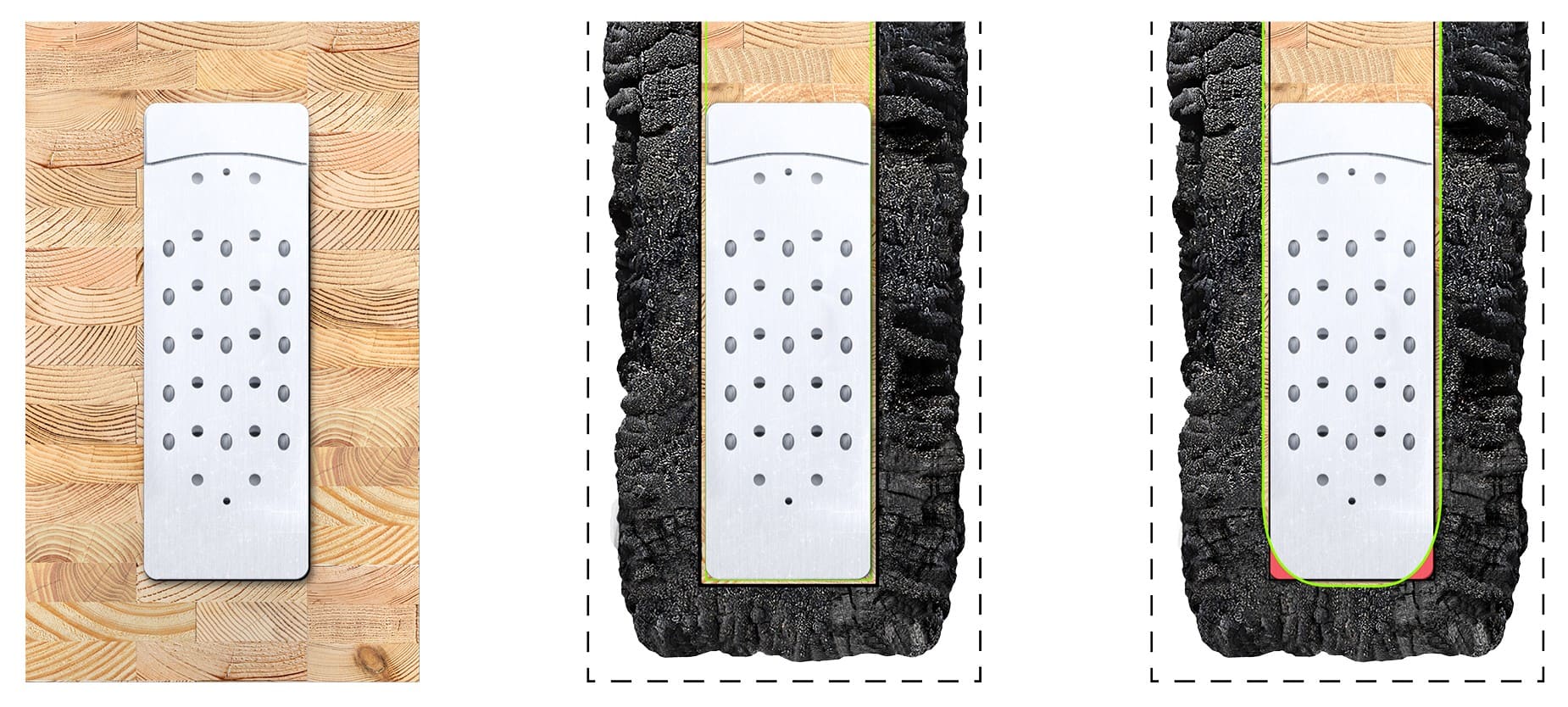
Figure 3. Effect of corner rounding on required timber cover for a concealed connection
Gap Requirements and Char Contraction
Once the effective cross section has been established, the designer must also account for the possibility of fire penetrating through joints between timber members. Gaps between members can create pathways for fire penetration and reduce the protection provided to concealed connection components.
TR 10 addresses this effect through char contraction. As timber chars, shrinkage of the char layer can expose previously protected surfaces within an unbonded joint. For unbonded wood member ends and edges, TR 10 accounts for this by assuming that ignition penetrates into the resulting gap a distance equal to twice the char depth, 2·achar.
Where char contraction does not create an exposed pathway to the connection, fire penetration is significantly reduced and the required protection depth, 𝑑𝑝, may be taken as 1.14·achar. In practice, fire-rated sealants, intumescent tape, glued wood interfaces, or other tested joint protection systems may be used to limit fire penetration through the joint and maintain the required protection around the connection.
CSA O86 does not explicitly address char contraction, bonded versus unbonded joints, or maximum allowable gaps within concealed connections. However, Annex B references TR 10 as a source of additional guidance, making it a valuable resource when evaluating these connection details.
Fire Testing and Validation
While calculation-based methods provide a practical means of establishing fire resistance, full-scale fire testing provides an alterative means of validating the performance of a specific connection configuration under fire exposure. Testing can establish less conservative fire-protection requirements than calculation-based methods, enabling more efficient connection configurations and reducing the material required to achieve a specified fire-resistance rating.
MTC Solutions has conducted extensive fire testing of concealed beam hanger systems to establish fire-rated configurations for use in project applications. To learn more about this testing and the development of MTC’s fire-rated APEX Beam Hanger System, see “Inside R&D — APEX 2-Hour, Full-Frame, Fully Loaded Fire Testing”.
For more information, MTC’s Beam Hanger Design Guide provides complete detailing requirements to simplify the design of concealed and fire-rated connections. The guide includes minimum cross-section requirements for concealing the MTC beam hanger systems while achieving 45-minute, 1-hour, and 2-hour fire-resistance ratings.
If you have any questions, contact our Technical Support Team 🙂
Register for a Technical Learning Session
Sign up for MTC Newsletter and keep up to date with all our progress.