In mass timber construction, beam hangers are often used to connect beams to various structural elements like other beams and columns. However, in certain scenarios with lower load demands, screw crosses may offer a more cost-effective alternative.
Approximately a 5-minute read
Cross-laminated timber (CLT) flooring systems spanning 30 feet or more are being increasingly adopted in North American mass timber construction. Their popularity can be partially attributed to their ability to reduce the need for columns—a crucial factor in maximizing usable floor space.
While long-span, high-ply count CLT flooring systems supported by a single beam system can generally withstand anticipated loads, their extended length may amplify vibration issues, potentially impacting occupant comfort. To solve this problem, a composite beam system may be employed, as illustrated in Figure 1.
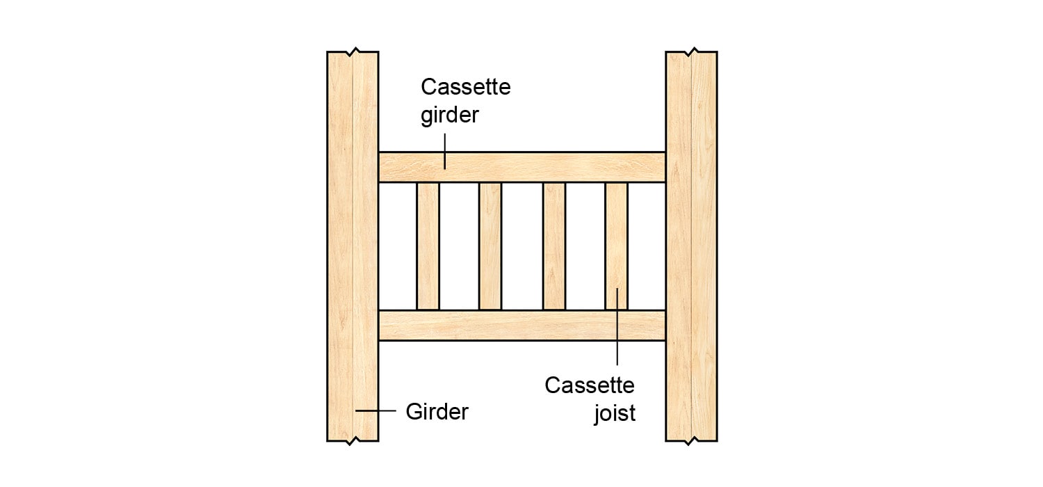
Figure 1. Plan view of a composite beam system
Owing to their high capacity and ease of installation, beam hangers are generally the preferred choice for establishing connections between beams themselves and between beams and columns in mass timber structures. In the above example, pre-engineered connectors, such as beam hangers, would normally be used to connect the cassette girders to the girders and the girders to the columns (not shown). However, in scenarios where lower load demands are expected, such as the cassette joist-to-cassette girder joints in Figure 1, beam hangers may not be the most cost-effective solution. In such instances, screws alone emerge as an appealing alternative, offering cost benefits that often outweigh considerations related to their lower load-bearing capacity and the need for more stringent installation controls. Nevertheless, when opting for screws to directly connect structural elements, it is important to consider several key factors, mainly including thread ratio, arrangement, and installation angle.
Thread Ratio and Arrangement
Fully threaded screws should be selected for their superior withdrawal capacity in both primary and secondary members. To ensure stability, these screws should be used in pairs, forming what is known as screw crosses. Each cross consists of two screws symmetrically arranged around the neutral axis of the secondary member. For more details on screw crosses, refer to our previous blog post, “A Brief Note on the Application of Screw Crosses.”
Installation Angle
The angle at which screws are installed plays a significant role in the internal force mechanics in the wood members. Here, a cassette joist-to-cassette girder connection established with one screw cross is used for explanation.
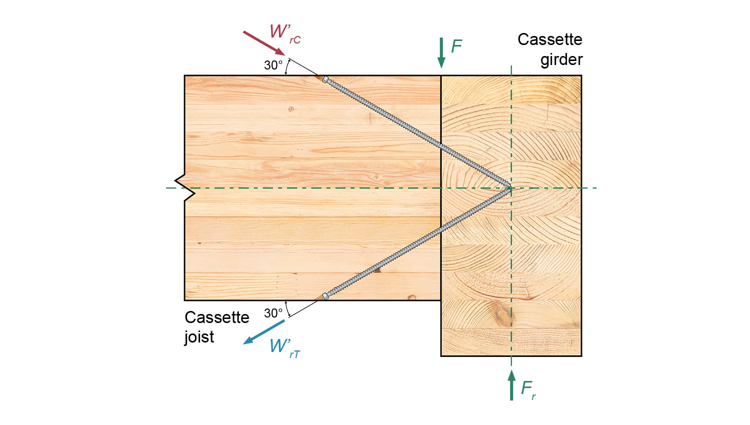
Figure 2. Elevation view of a cassette joist-to-cassette girder connection established with a pair of screws installed at 30°
When screws are installed at a shallow angle, specifically less than 45°, the vertical shear force (F) on the cassette joist is assumed to be entirely transmitted to the cassette girder through a compression component (W’rC) and a tension component (W’rT) via the top and bottom screws, respectively. Notably, it is generally accepted that the transmission of the compression component—critical for equilibrium maintenance—is solely achieved by the top screw, without the need for a direct load path between the two members.
In this configuration, the induced torsion is typically applied to the primary member, that is, the cassette girder. To counteract this torsion, a screw arrangement is needed that allows all the forces—W’rC, W’rT, and the reaction force (Fr) of the cassette girder—to intersect at the neutral axis of symmetry of the cassette girder.
The initiation of screw engagement at a shallow installation angle, however, relies on the occurrence of deformation. Only through deformation can the screws be engaged in tension. Given that deformation, however small, is undesirable, this precondition may pose challenges in real-world applications.
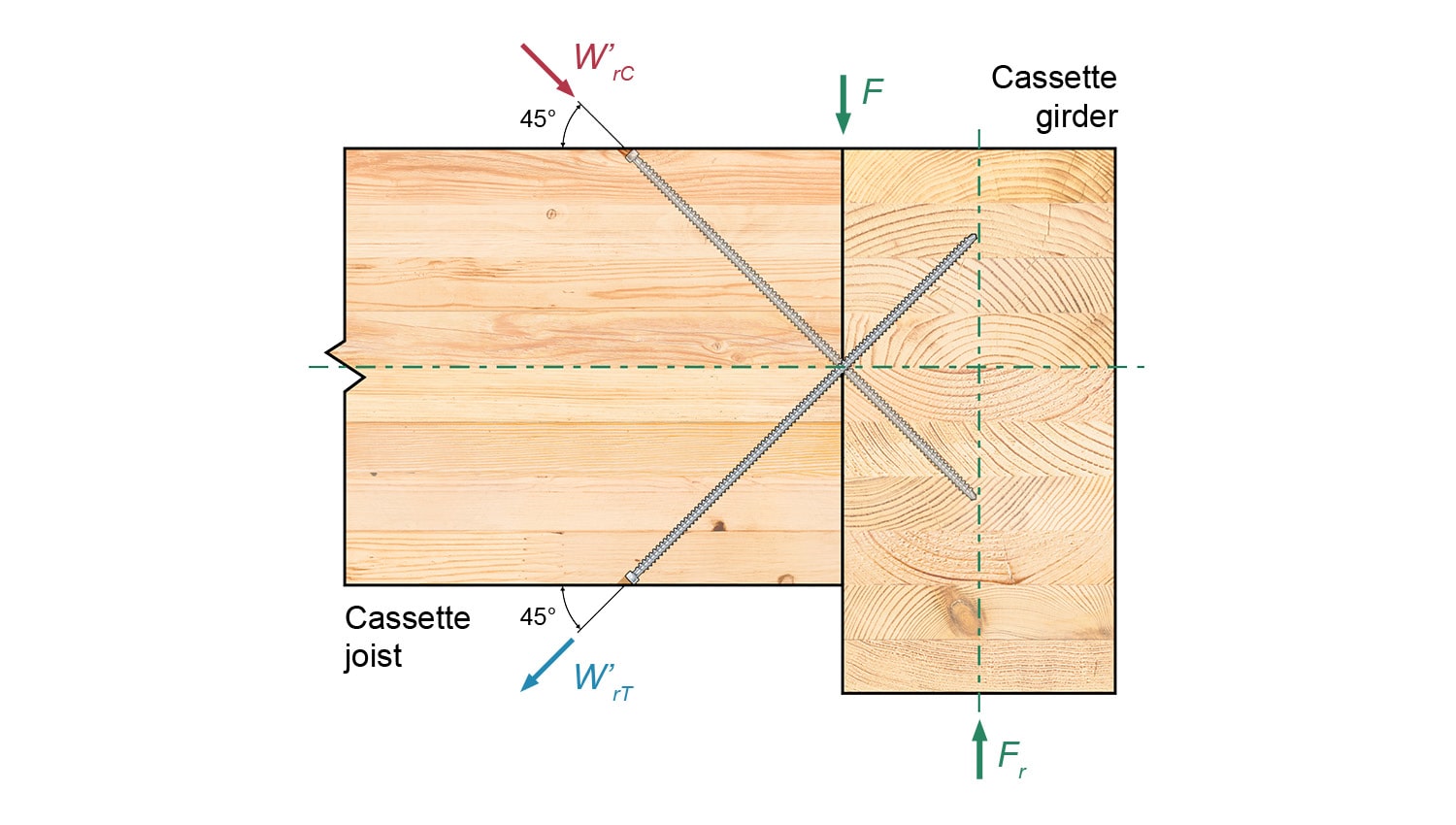
Figure 3. Elevation view of a cassette joist-to-cassette girder connection established with a pair of screws installed at 45°
In practice, the need for deformation can be eliminated by inserting the screws at a 45° angle, as shown in Figure 3. This adjustment in the installation angle transforms the force mechanics, giving priority to withdrawal over shear, in contrast to the scenario with a shallow-angle installation.
This commonly adopted method positions the screws to intersect on the shear plane of the two wood members at their interface. To prevent collision, the screws must be symmetrically arranged with an equal offset from the neutral planes of the secondary member.
Unlike the case with a shallow installation angle, achieving force equilibrium with screws at a 45° angle mandates a direct load path from the cassette joist to the cassette girder. This path facilitates the establishment of a compression face between the two members, a vital development enabling the screws to immediately bear the shear load. This approach eliminates the reliance on deformation for load transfer, as would be the case in the absence of a direct load path.
While pre-engineered connectors, such as beam hangers, support faster installation processes, and offer higher load-carrying capacity in mass timber construction, screw crosses can offer a more cost-effective solution for certain joints with lower load demands.
If you wonder what the most efficient design for your project would be, contact our Technical Support Team for more information or design guidance. 😉
Register for a Technical Learning Session
Sign up for MTC Newsletter and keep up to date with all our progress.