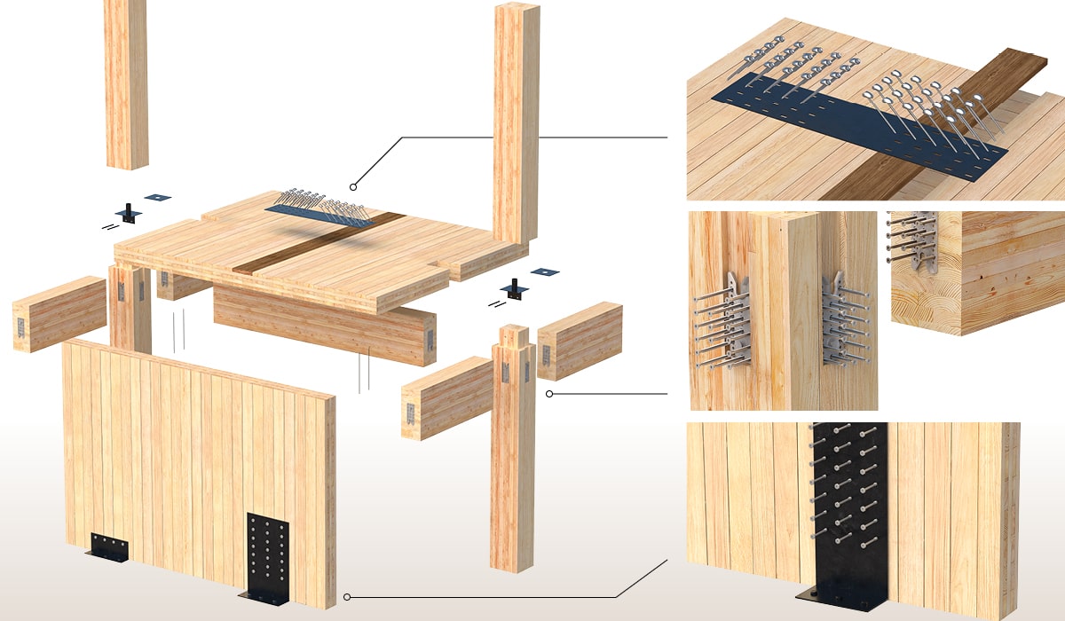
Mass Timber is increasingly being used in larger scale commercial construction on an institutional, industrial, and residential mid to high-rise level. With this comes the need for an efficient building design, and its connection technology is no exception. Besides the desire to reduce cost and construction time, we must also obtain the desired building performance while maintaining a sustainable forward-thinking mindset throughout the process. Safety is always a high priority when it comes to connection design, however, using excessive amounts of fasteners can trigger the exact opposite since a connection may not behave the way we intend it to behave.
In mass timber framing systems, the most common connection types are:
Understanding the different failure modes of structural self-tapping screws (STS) in these configurations is essential for any designer working on a mass timber project. This blog post investigates connection detailing considerations for these configurations.
Approximately 4-min read.
Understanding Mass Timber Connections Behavior
The first step in understanding mass timber’s connection behavior is understanding how fasteners behave in connecting systems, but why is that? Looking below, we have a basic overview of where fastening technology for connections can be used. In fact, they are currently an essential element in all types of designed solutions: posts and beams, wall and floor panels, straps, and plates, in wood-to-wood, and steel-to-wood configurations.

Please note that the below-mentioned behaviors are for monotonic loading only. Under dynamic conditions, fasteners behavior and failure modes may vary.
Detailing Considerations
When detailing connections to meet performance expectations, a variety of factors must be taken into consideration.
First, the geometry requirements such as end and edge distances should be determined, with special attention on establishing whether they are loaded or unloaded end or edges. It is even more critical when connections are designed in wood species that are more sensitive to splitting, such as Douglas Fir or Fir. Another key boundary factor to account for is the thickness of the mass timber main and side members. Indeed, to develop the desired yield mechanisms in the fasteners, a certain minimum embedding below and above the shear plane is required. Depending on the fastener diameter, this minimum embedding varies. The picture below exhibits this.

1/4″ [6 mm] and 1/2″ [12 mm] diameter fasteners that have been loaded with appropriate embedding in the main and side members clearly produce the desired failure mode 4, where two plastic hinges are formed. One can also observe typical head pull-in of the 1/4″ [6 mm] diameter countersunk head fastener on the left, which occurs where the fastener’s deformation and the yielding shear force transition from a perpendicularly applied force into a portion of axial pull.
When computing connections with common design standards, the correct prediction of the expected failure mode is often obtained, however, the magnitude at which this failure mode will occur often does not match accurately.
While wood-to-wood connections are rather simple to install for the most-used partially threaded STS [up to 16” [400 mm] length], steel-to-wood connections can be a lot less forgiving, and more attention may be required by the installer to reduce the risk of injury and/or fastener breakage. Steel-to-wood connections set the screw head against a hard surface which will not allow countersinking of the screw head into the timber, as seen above, resulting in a sudden installation stop and a significant torque increase, with feedback to the installer.
In addition to this torque feedback, detailing of steel-to-wood connections must also consider the appropriate predrilling hole diameter in the steel member, under the considerations of connection slip and selected steel plate coating thickness.
A complementary blog about Detailing steel-to-wood connections with ASSY Self Tapping Screws will provide the necessary information to understand standard mass timber connections’ behavior in steel to wood configuration. You can also refers to the “Appendix E: Steel Plate Detailing” on page 88 of our Structural Screw Catalog.
If you have any further questions, please contact our Technical Service Team 🙂
Register for a Technical Learning Session
Sign up for MTC Newsletter and keep up to date with all our progress.