
MTC Solutions’ MEGANT series is a line of pre-engineered beam hanger connectors designed for mass timber structural applications. This article provides installers and manufacturers with the best installation steps for the MEGANT connector series. This includes general considerations for the installation, the hardware and tools necessary, installation time, and step-by-step instructions to ensure optimal performance and a safe, secure connection.
New to designing with mass timber post-to-beam connections? Read this article first to learn more about beam hanger systems.
Approximately 10-minute read.
Hardware & Tools: What do You Need?
Every MEGANT connector set is delivered with:
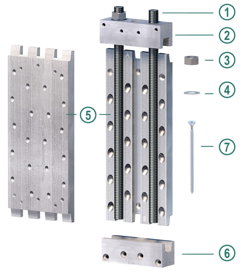
Figure 1. MEGANT product kit details
For an accurate installation, MTC recommends using:
And the usual must-haves; PPE, a measuring tape, a framing square, and a marker.
Installation Time and Time-Saving Tips
The estimated time for a single person to install a MEGANT system is about 15 to 45 minutes depending on the model, which can be improved further by mastering efficient practices such as predrilling, using the proper jig, and optimized beam positioning.
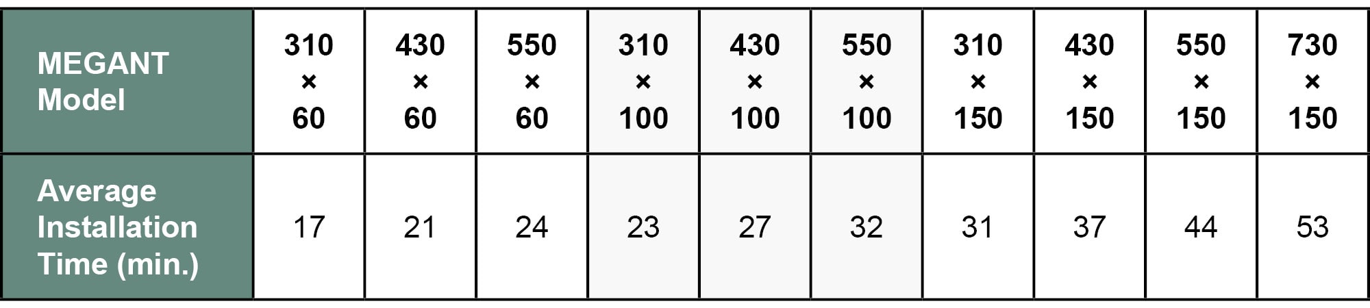
Table 1. MEGANT installation time, by model
The installation times given in the above table include:
💡 Installation Efficiency Pro Tips
Step-by-Step Installation Instructions
Before diving into the step-by-step installation process of the MEGANT series—especially if you are not familiar with MTC Solutions fastener technology—we recommended you read through our STS installation best practices article that details how to optimize your installation.
Additionally, the following step-by-step guide is available for free download, in a printable black and white format, practical for on-site teams => Go and download!
Now, let’s get started!
1. MEGANT plate and clamping jaw layout and reference points
Before beginning with the layout and orientation of the connector’s plates and clamping jaws on both the primary and secondary members, please verify the secondary member’s on-site installation orientation, as it may impact some aspects of the installation process.
Indeed, the MEGANT connector has the benefits of being concealed, and can be installed in a wide variety of configurations, and from all directions; drop down, from below, and from the side. This installation orientation will dictate the positioning of each clamping jaw in the connection, therefore, we suggest installers refer to section 3 of this article, Clamping Jaw Installation, for a complete overview before proceeding.
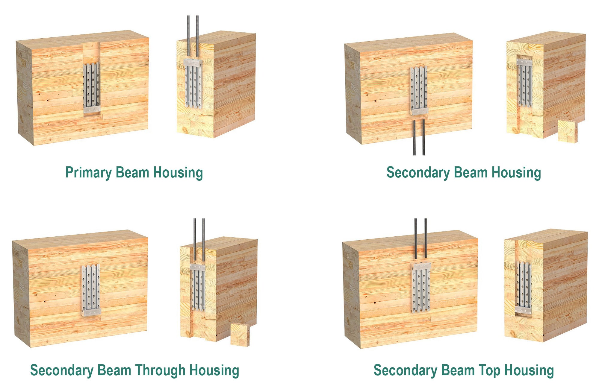
Figure 2. MEGANT housing configurations
The MEGANT’s point of reference is the top of the beam. Each MEGANT plate is marked with an “A” on one end and a “B” on the opposite end. Hence, when the inclined screws of the MEGANT are installed, they will incline so the heads of the screws are facing the end of the plate marked with a “B”, and the tips are pointing towards the end of the plate marked with an “A”.
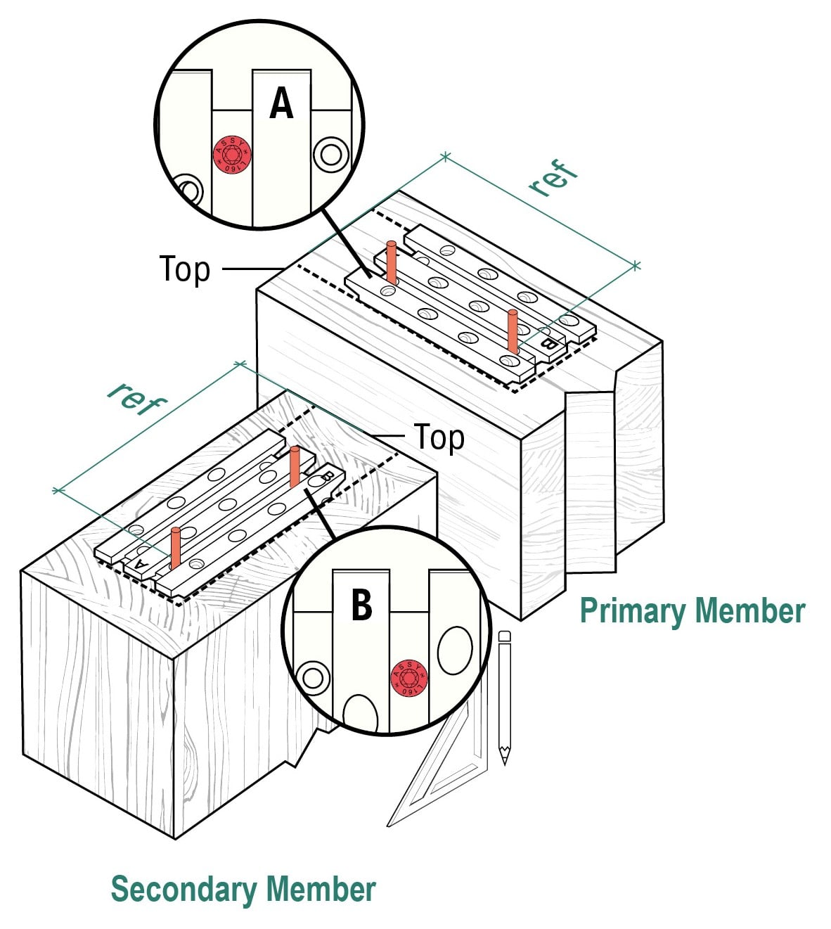
Figure 3. MEGANT placements on primary and secondary members
It is critical to install the connector plates with the correct orientation on both members, as the capacity of the hanger is dependent on the inclined fasteners being loaded in tension.
💡Key Considerations
2. Structural Screws Layout, Sequencing and Best Practices
Start by installing the two structural positioning screws through each plate—red dots in the infographic below—which will hold the connector in place during installation of the remaining fasteners. Then proceed with installing the horizontal screws in the plates, then the 45° inclined screws, and finally the horizontal screws through the clamping jaws. Please refer to Section 3 of this article, Clamping Jaw Installation, for a complete overview before proceeding.
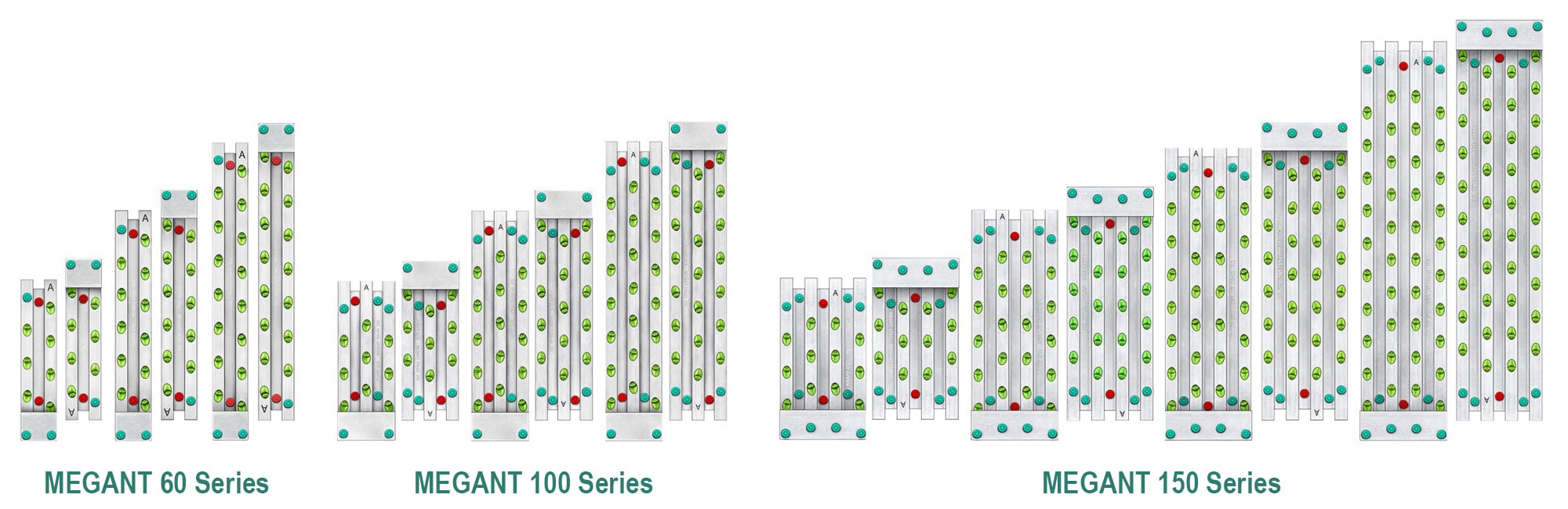
Figure 4. The screw pattern for each MEGANT series
For an optimized installation process, we recommend that each screw is installed considering the following best practices:
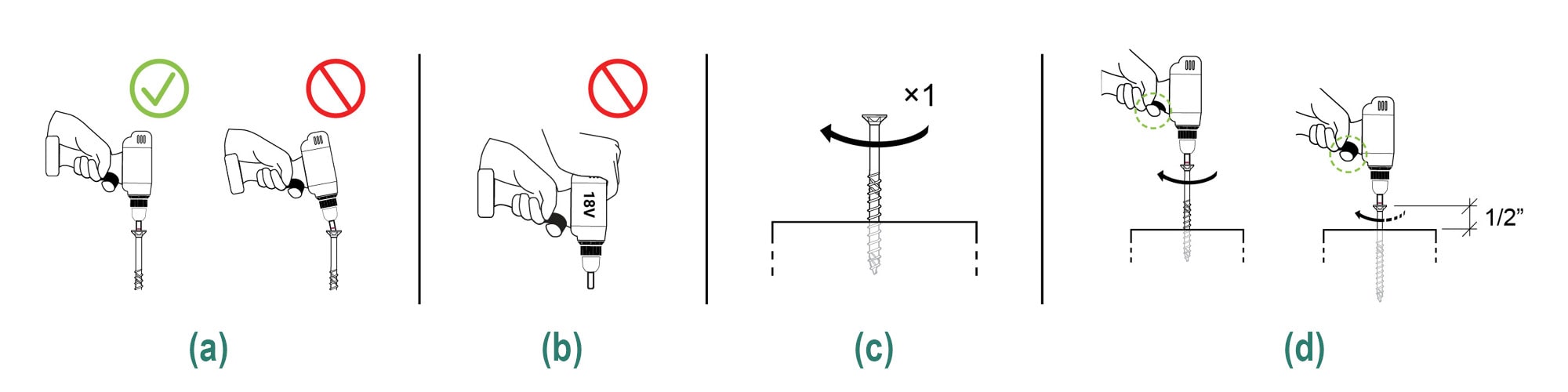
Figure 5. Screw installation best practices
💡 Pro tip, predrill pilot holes!
Although not mandatory, drilling pilot holes before installing STSs is highly encouraged as it helps to:
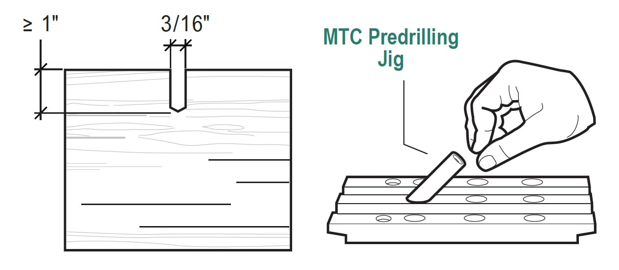
Figure 6. Pilot holes with MTC’s Predrilling Jig
Including this step in your installation routine, especially during repetitive or multi-unit installations, can greatly improve efficiency and consistency. For the 5/16 in. STSs used with the MEGANT, it is recommended to predrill pilot holes with the following dimensions:
3. Clamping Jaw Installation
Each MEGANT kit comes with two clamping jaws: a threaded one and an unthreaded one, which need to be installed on opposite ends of the MEGANT plates. The unthreaded clamping jaw MUST remain accessible after the secondary member is positioned on-site to allow for the threaded rods, nuts, and washers to be installed and tightened by the site crew.
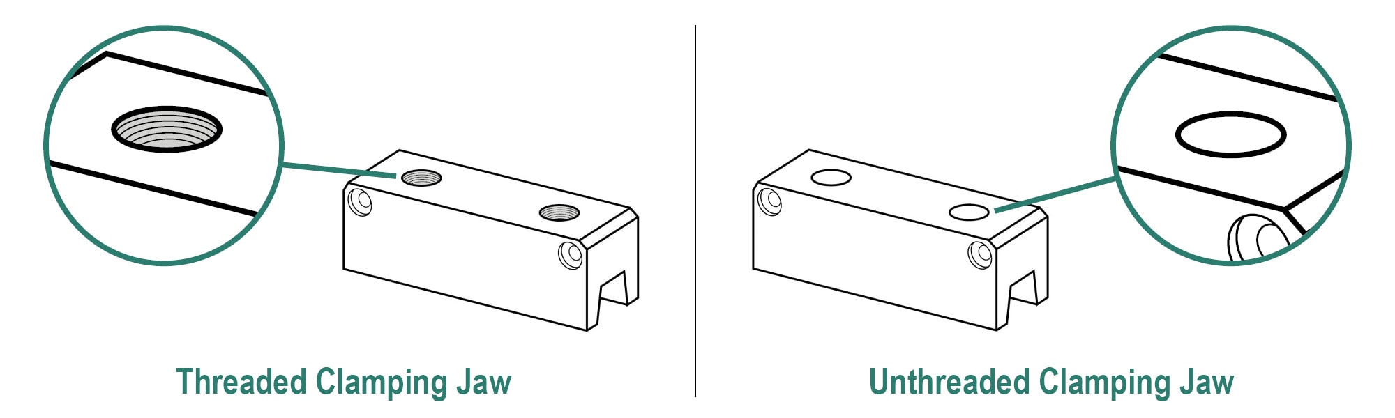
Figure 7. MEGANT Clamping Jaws
As mentioned earlier in this article, the MEGANT connector has the benefit of being installable from multiple directions. The installation direction will dictate the positioning of each clamping jaw on the assembly. Here are a few items to consider when reaching this step:
The position of the unthreaded clamping jaw varies based on the housing solution selected. In a regular drop-down installation configuration, two options exist:
In installation configuration from below, with an open-top housing in the secondary member, the unthreaded clamping jaw must be installed at the top end of the assembly on the primary member.
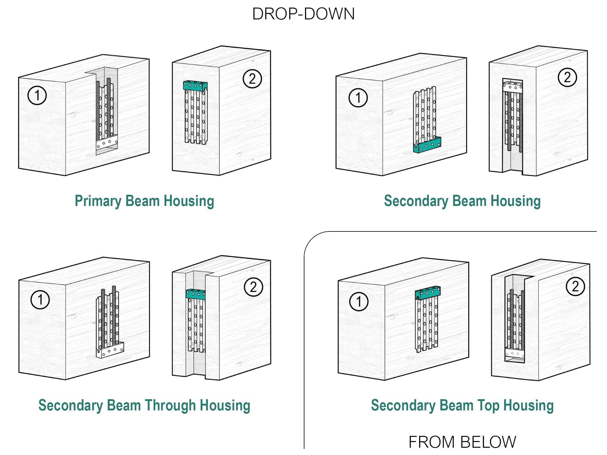
Figure 8. MEGANT unthreaded clamping jaw placement for each installation type
For the installation itself, the clamping jaws are to be installed with the countersunk holes facing away from the member to which it will be fastened. Firmly sit the jaw’s grooved side against the tongue of the MEGANT plate, at either the “A” end or “B” end depending on your configuration.
4. Connecting the MEGANT Plates
Slide the secondary member into place until the MEGANT plates on the secondary member are aligned with the MEGANT plates on the primary member.
Then, insert the end of the threaded rod that doesn’t have a hex head recess in the clamping jaw.
With the jaws are properly seated, the threaded rod will reach the end of the unthreaded jaw holes with 2-3/8 in. [60 mm] of its length protruding, if it’s less, it means the jaws are not fully seated. In such a case, adjust the position of the secondary member as necessary.
Once this has been achieved, drive in the threaded rod until 1-3/16 in. [30 mm] of its length remains protruding. Place the washer(s) then install the hex nut(s).
Repeat the process for all threaded rods. Once all threaded rods are installed, tighten the nuts using the recommended torque of 29.5 lb. ft.

Figure 9. Connecting the MEGANT assembly
A Key Consideration for connectors housed in the secondary beam is to fill in the routed void below the connector for aesthetics and fire protection once the assembly is in place. A wood plug may be used, and installation instructions must be provided by the Engineer of Record.
Wow! You made it to the end; you’re one of a kind… 🎉 Congrats!
And remember, if you have any questions, our engineering team is here to help and support you, so don’t hesitate to contact us 😄!
Register for a Technical Learning Session
Sign up for MTC Newsletter and keep up to date with all our progress.