

While general rigging guidelines—like those detailed in our previous articles, “Rigging Device Installation: Essential Tools and Top Tips” and “How to Ace Rigging Safety Checks: Simple, Efficient, Proven Steps”—are often sufficient, certain scenarios in mass timber projects require specialized approaches. In this article, we explore three unique rigging cases you might encounter: wall panel tilt-up, columns, and deep beams.
Read on to learn practical techniques to help you navigate these situations efficiently and safely.
Approximately 7-minute reading time.
Wall Panel Tilt-Up
CLT wall panels can be tilted into place by lifting them from a horizontal to a vertical position. This is usually achieved by attaching anchors to either the edge or the face of the panel at one end, while the other end bears on a stable surface for support. The lifting capacity of each orientation must be reviewed as they may not be equivalent. Panel tilt-up should only be completed by an experienced, qualified rigger following an engineered lifting plan.
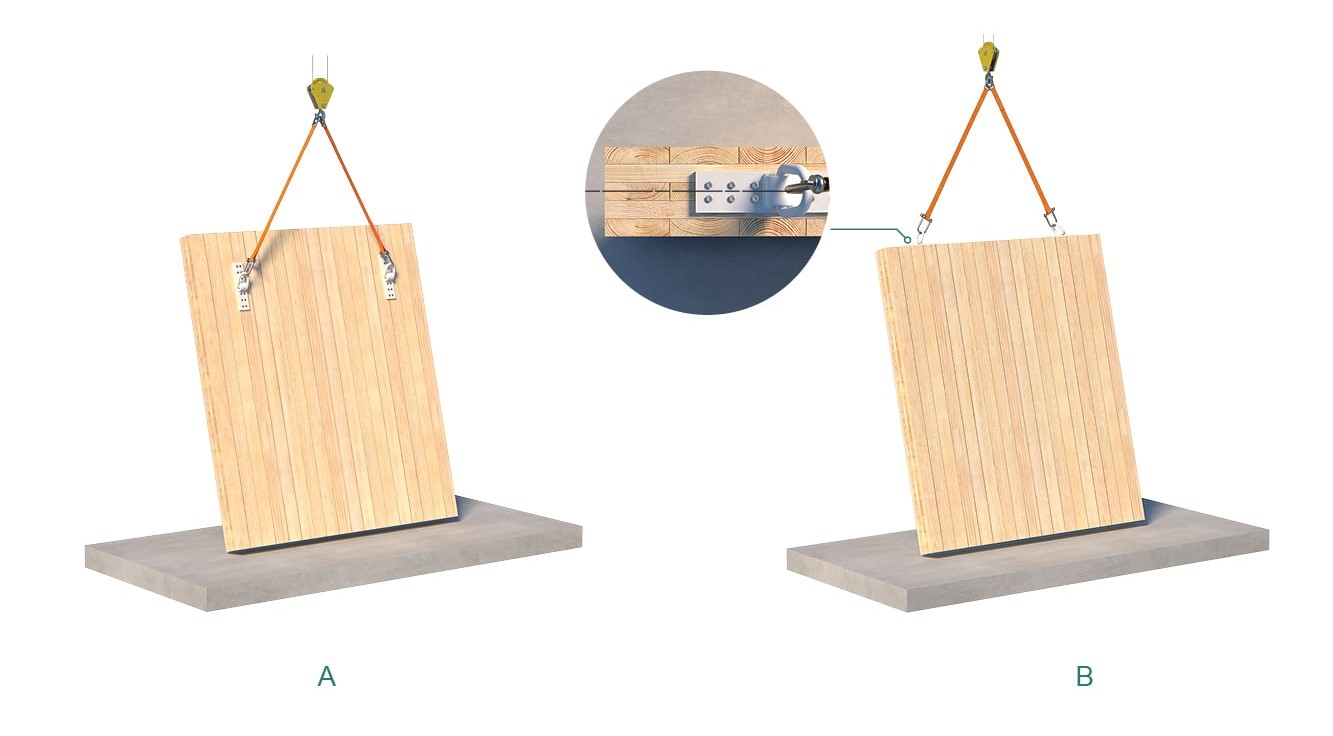
Figure 1. Anchors installed on the (A) face and (B) edge of a panel in a tilt-up operation
Key Consideration: Sling Angle, β
The angle between the sling and the panel surface, the sling angle, β, is key to a safe lift. Maintain β ≥ 60° for optimal sling tension and loading. To ensure you have achieved this sling angle, measure the distance between your two anchors and compare it to the length of one leg of your hitch. To maintain β ≥ 60°, the leg length should be equal to or greater than the length between the two anchors. Note that, to check this angle, the hitch should be pulled tight but should carry no load, while the panel is stable in its pre-lifting position.
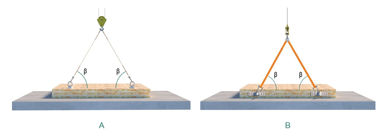
Figure 2. Proper methods for measuring sling angle (β) when anchors are installed on (A) the face and (B) the edge
Note: When installing anchors, consider end and edge distances and place them along the midline to minimize splitting risk.
Why does β matter? It affects two important factors:
A β below 60° simultaneously increases anchor demand and decreases anchor capacity, making it crucial to properly measure and maintain β ≥ 60°.
For detailed calculations on demand and capacity, consult our Rigging Design Guide (Pages 15–17) or reach out to our Technical Support Team for assistance.
Column Lifting
Lifting columns can often be precarious for a few reasons:
These characteristics limit picking points to the top end of the columns where rigging screws installed in end grain have a much lower capacity in tension and require experienced timber riggers. There are two primary methods for lifting columns often observed on site.
1. Using Preinstalled Connectors
Columns below roof level typically come with a preinstalled column-to-column connector that can serve as a convenient picking point. This method is efficient and straightforward—just make sure a qualified rigging professional verifies the connector is suitable and engineered for such a lift.
2. Using Anchors
When preinstalled connectors are unavailable, anchors can be installed on the top end of the column for lifting. There are two types of anchors to consider:
(1) Slide-On Anchors—Transport Anchor
The Transport Anchor is a potential option for lifting columns. It slides onto and off of a single 1/2 in. [ 12 mm ] Kombi LT screw, allowing for quick installation and removal. In some cases, a second Transport Anchor with a screw installed at a 45° angle opposite to the tilt-up direction may be recommended.
(2) Screwed-In Anchors
While capable of higher capacities, screwed-in anchors require at least four screws and often need machinery like scissor lifts for removal. This makes the process more time-consuming and less cost-effective due to increased crane time.
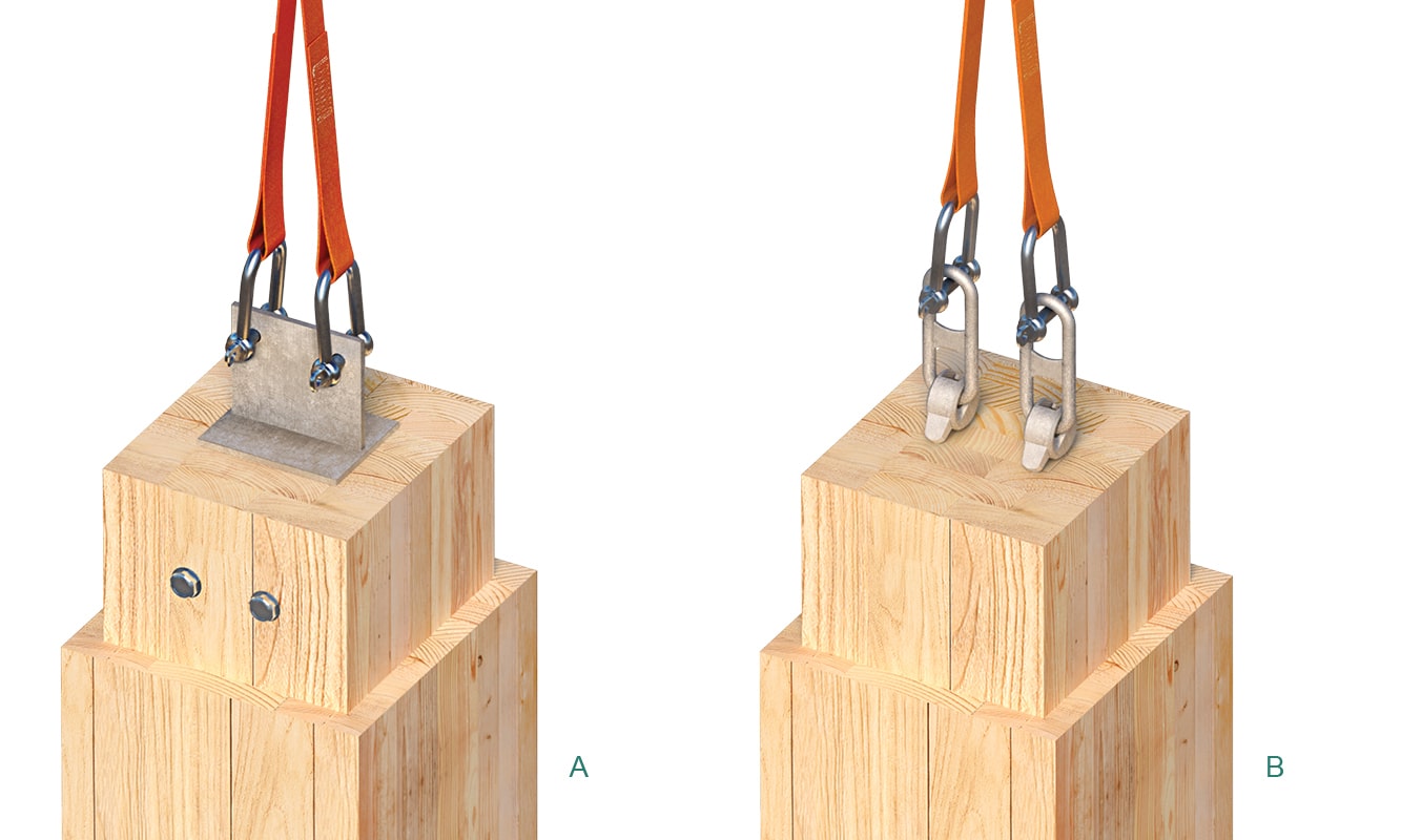
Figure 3. Column rigging using (A) a column-to-column connector and (B) the Transport Anchor
Overall, due to variability in end-grain wood conditions at column ends, tabulated data is not typically provided for rigging columns. While custom column yokes have been designed for specific projects, generalized values are unavailable. For projects involving extensive column rigging, contact our Technical Support Team for advice on a rigging solution.
Deep Beam Rigging
We recommend the Yoke XL, our heavy-duty anchoring system, for lifting deep beams. In this application, perpendicular-to-grain tension remains a main concern due to its potential for causing splitting.
Solution: Use the longest possible fasteners to ensure strong thread engagement in the deeper laminations of the beam.
Note: Longer fasteners can shift the governing limit state from wood withdrawal to steel tension. Withdrawal values are based on a factor of safety of 5, consistent with the factor of safety required for rigging applications by authorities such as OSHA, HSA, and WorkSafeBC. Steel tension values, however, are based on a factor of safety of 3. Accordingly, where steel tension governs, the tabulated design value may require further reduction to satisfy the required rigging factor of safety. The tabulated values also do not account for perpendicular-to-grain splitting under the screw tips.
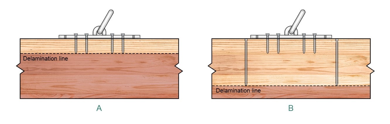
Figure 4. Deep beam rigging (A) without and (B) with reinforcing screws
Solution: Consider using tabulated design values where applicable and adding reinforcement with VG CYL or RH fasteners around the picking points to mitigate splitting. The reinforcing screws can improve resistance to splitting forces across their entire length. They should be installed in such a way that the forces are carried through the entire beam depth.
If you have any questions about our rigging systems or need help with rigging planning, contact our Technical Support Team 😉.
Register for a Technical Learning Session
Sign up for MTC Newsletter and keep up to date with all our progress.