Approximately 10-minute read.
The current state of standardization for mass timber fasteners currently requires us to draw parallels and create analogues to lag screws. In North America, supplementary documents like ICC ESR’s and CCMC reports fill in the gaps and specify the requirements for many applications of self-tapping screws, as we have seen with geometry requirements. Just as unthreaded and threaded shank diameters play a critical role in predrilling and determining group spacing, they also serve as the basis for other strength parameters in mass timber connections.
To reiterate, the current practices are that self tapping screws are implicitly allowed per the NDS and CSA (ignoring the acceptance through ICC or CCMC) as a lag-screw. In this blog we hope to share and explain some of the implications of this when it comes to design, as they specifically relate to:
This is Part 2 of a two-part series providing some background information for ASSY screw connection design and North American design standards; find Part 1 here.
Self tapping fasteners have paved the way for the meteoric rise of mass timber, but while these screws are now used in every project, their design in connections is not always straightforward due in part by the lack of references in North American design standards. This is particularly true in American design where all fasteners are grouped together in a category with a single calculation method.
Shear Strength vs. Lateral Design Values
In our guide we provide screw shear values along with the tensile and bending yield strength of the case-hardened steel that the screws are made of. These shear values often get confused for design values of STS in laterally loaded connections in wood – this is not the case. This shear value is simply another material property and is not typically used in design equations; STS can display several different behaviours and failure modes depending on several primary factors including fastener slenderness, embedment length, angle to grain, and wood density. It would also be important to note that the lateral connection resistance will not exceed the shear resistance in the typical range of design loads, though this is sometimes seen at very high deformations for high quality fasteners like the ASSY screws.
These factors are captured in lateral yield strength equations in CSA O86 and the NDS 2018, derived from the work of Johansen in the 1940’s. These equations have consistently proven suitable estimation for the strength of dowel-type connections and predicting the failure or yield mode of the fastener in wood:
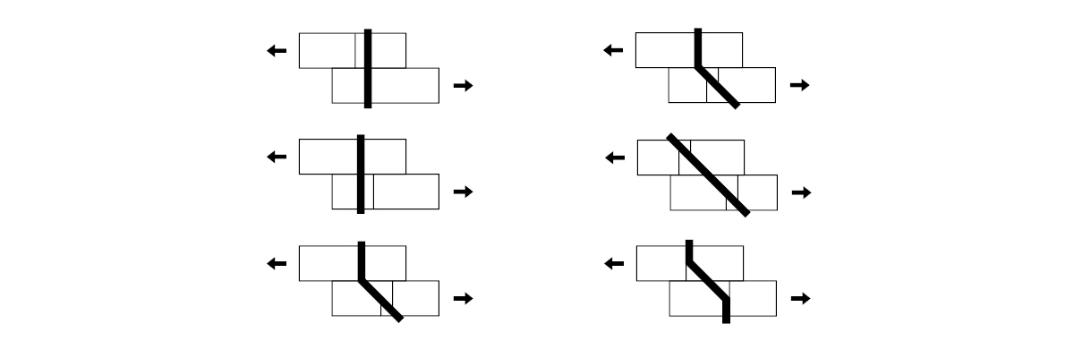
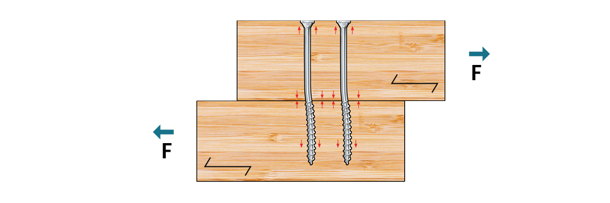
Rope Effect
As we have mentioned in previous blog posts, STS are considered as lag screws for the purpose of lateral connection design in both CSA O86 and the NDS 2018 while withdrawal design capacities are captured in product approvals (CCMC, ICC-ESR). These lateral design equations adapted from Johansen in clauses 12.6.6 and 12.3 of CSA and the NDS, respectively, capture dowel and wood crushing effects but do not yet capture axial effects. These axial effects will only come into effect at a certain level of deformation.
For yield modes involving certain types of fastener yielding, a plastic hinge will form with a displacement along the screw axis on either side of the wood-wood connection interface. The axial capacity of the fastener then becomes engaged, generating a normal force that pulls the connected members together which produces friction in the shear plane. With significant deformations, the tension component of the fastener contributes additional connection strength. Slender fasteners with high axial and plastic capacities have inherent potential to contribute additional connection strength to shear connections through the rope effect. Design standards in Europe contain provisions for the additional strength contribution of the rope effect through a correction term to the yield model equations [EC5 Cl. 8.2.2 (2)]. CSA O86-19 incorporates the rope effect in clause 12.11 for wood screws through embedment strength f3 where the failure mode is fastener yielding. This has the design implication of boosting the capacity of the lateral connection with an additional strength of a quarter of the withdrawal resistance up to double the lateral resistance in whole.
At present, the lateral connection design procedure for self-tapping screws follows conventional Yield Limit Equations in NDS 2018, and Cl. 12.6.6 for lag screws in CSA O86, both of which do not include provisions for the rope effect.
Screw Diameter Classification
We previously mentioned wood screws which are referenced in clause 12.11 of CSA 086-19 and 12.1.5 of the NDS 2018 where in both cases they have some strength advantages over lag screws. There are more similarities between the wood screw provisions and the nail provisions, than anything relating to lag screws with respect to the code. One such example of this is in the wood bearing strength for lateral design, where the capacity is not assumed to vary with the load angle to the grain on account of the smaller diameter of these fasteners. This is absolutely not the case with self-tapping wood screws for mass timber construction.
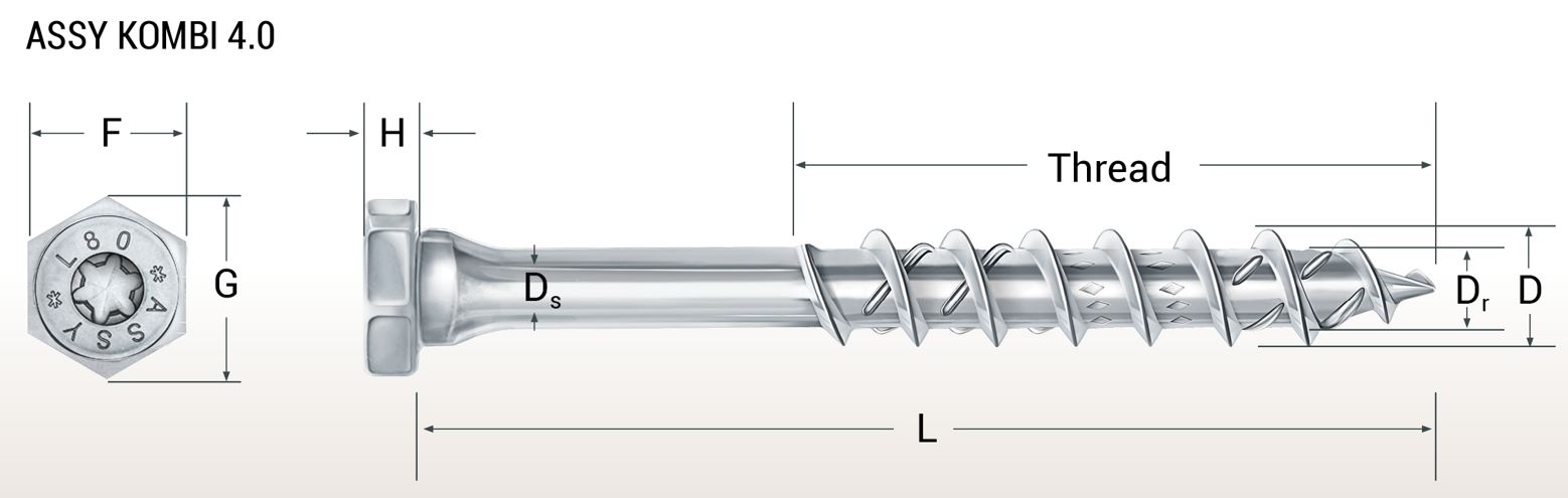
These smaller diameter screws meet the requirements of ASME B18.6.1. Tolerances for gauge 12 screws allow for a maximum outer thread diameter of 0.220″ [5.59 mm] and a minimum body (or “root”) diameter of 0.165″ [4.19 mm] for screws with rolled threads. The minimum size for ASSY® screws has a major outside thread diameter of 1/4″ [6 mm], with a root diameter of 0.154″ [3.9 mm] (partially threaded) or 0.150″ [3.8 mm] (fully threaded). Therefore, most engineered self tapping wood screws do not meet the size requirements pertaining to wood screws in CSA O86, and designers must not assign the outer thread diameter to the variable df in the yield limit equations of Clause 12.11.4.2 for the purpose of lateral connection design.
Which Diameter Do I Enter Into the Yield Model Equations?
Dowel bearing resistance and dowel moment resistance in laterally loaded fasteners is a function of diameter.
Yield model equations in CSA and NDS are idealized for dowels and don’t capture the essence of STS’ since bearing may occur at various locations along the screw—including at the threads. STS threads are manufactured from the original steel wire used for the screw body and are considerably wider than threads on traditional lag or wood screws. As the steel material from the wire is moved into threads, the resulting diameter of the threaded portion of the wire is significantly reduced. It is not adequate to take the listed thread diameter as D per standard details, this reduced section diameter (a.k.a. root diameter, Dr) must be taken instead. The only application in which the thread diameter is taken as D is for withdrawal strength calculations. Recent tests also show us that using the shank diameter (Ds) is accurate and still provides a great deal of overstrength, but this would not be following the guidelines of the current design standards in question.
Tabulated reference design values (see Structural Screw Catalog) for threaded fasteners in the NDS are based on the minor diameter for simplicity and conservatism. The American Wood Council Technical Report 12 (TR-12) suggests that smooth shank D of partially threaded STS can be taken when the smooth shank penetrates sufficiently far into the main member—for moment resistance. Procedure for this may be found in TR12. The NDS 2018 instructs shank D may be taken when it penetrates at least three quarters of the full Lm (cl. 12.3.7.2)
While STS are implicitly allowed as lag screws in mass timber connection design, there is a lack of references in design standards; supplementary documents like ICC ESR’s and CCMC reports fill some gaps and specify requirements. This can lead to some common confusion when it comes to pre-drilling specifications or the parameters that surround design values, we hope to have clarified some of these points.
We are actively engaged in testing and are collaborating with standards bodies along with other manufacturers to push engineering into a space where design information is accessible and recognized in a unified format. Until then, feel free to browse our resources and reach out to our Technical Service Team with your connection questions 🙂
Complementary information on how to design mass timber connections with MTC structural fasteners—with the above considerations in mind—are regrouped in our latest edition of the Structural Screw Catalog.
Register for a Technical Learning Session
Sign up for MTC Newsletter and keep up to date with all our progress.