Self-tapping screws (STS) were introduced into the market with one of many major benefits over lag screws being that pre-drilling is not required. In many cases one would be correct in thinking that they do not, but in other instances pre-drilling is a critical component of a successful mass timber connection with self-tapping screws.
This blog post provides CSA O86-19 and NDS-2018 based context on the current provisions that govern pre-drilling recommendations for self-tapping screws in mass timber design.
Approximately 6-minute read.
Self Tapping Screws Treatment in Modern Timber Codes
Since mass timber has been introduced into the North American market, design standards have not been completely updated to reflect the swathe of new connection technology that has followed this introduction. Designers must make do with determining which geometry requirement provisions apply to self-tapping screws – which serve as a governing analogue for the use of STS’ in design. This analogy is not perfect, and thus supplementary documents such as technical approvals, ICC, CCMC, or ETA, are used to fill in some of the information gaps in design intent and instruction. Currently, pre-drilling for STS’ is one of the knowledge gaps that is not fully supplemented by approvals, therefore designers are left to interpret the provisions for lag screws in these cases – and sometimes foregoing the benefits that pre-drilling can bring to a connection detail. If a connection is designed without pre-drilling, pilot holes may still be used to facilitate installation (a link to pilot hole guidelines can be found at the end of this tech blog).
Pre-drilling for STS’ in mass timber connections serves one of two primary functions.
Background on Pre-Drilling Requirements
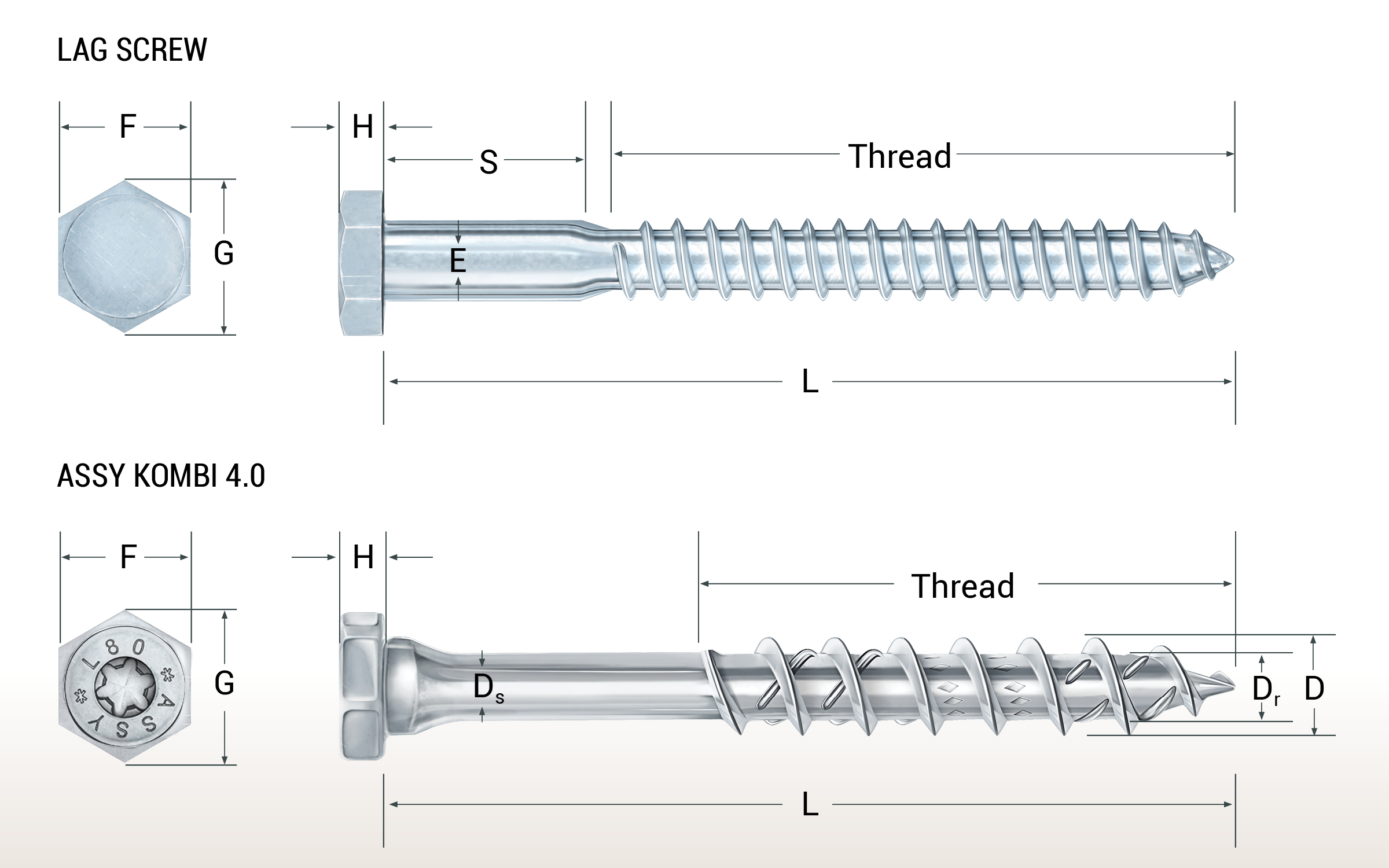
In CSA O86-19 and the NDS-2018, references are made to ASME B18.2.1 which provides geometry information on typical lag screws that the design standard covers. It is important to look at both the body or shoulder diameter specified within as well as the diameter of the unthreaded and threaded shank. These features are referenced in CSA and the NDA as the guidelines for which pre-drilling is specified and performed – again, a clear translation can be inferred here based on the same diameters of STS’.
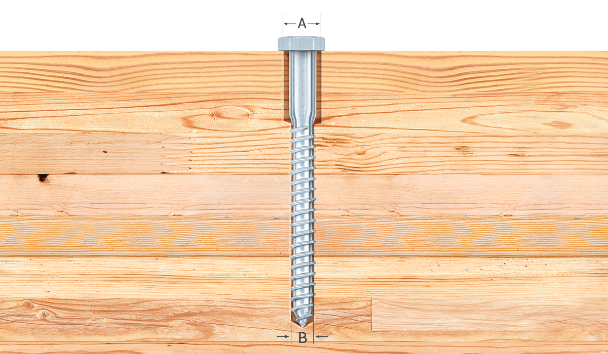
The pre-drilling requirements covered in the Structural Screw Design Guide (Canada) relate to CSA O86-19 clause 12.6.2.1(b) referring to pre-drilling of the lead hole for the complete threaded portion of a lag screw with the following percentage ranges relating to the shank diameter:
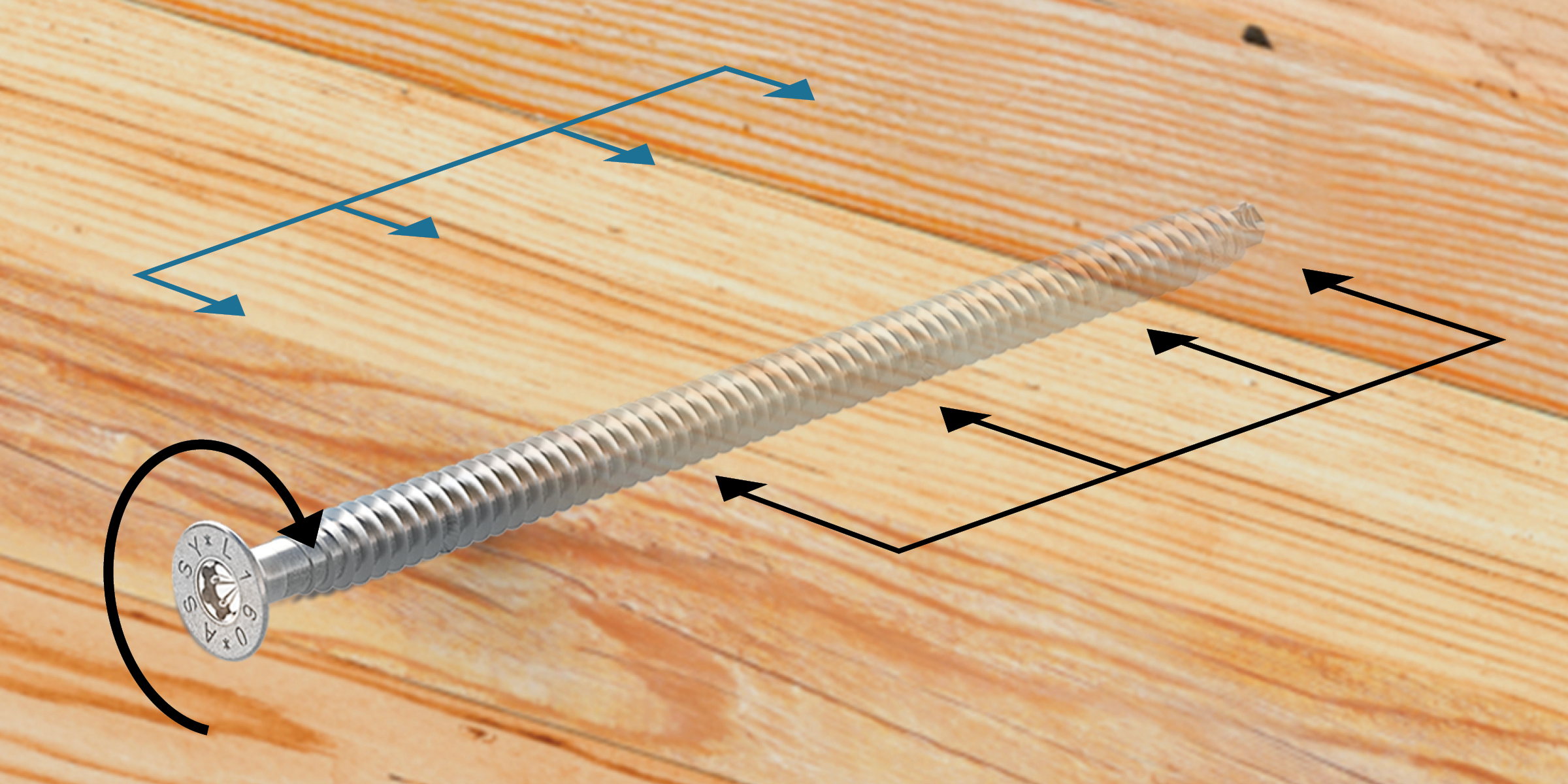
This range of shank diameter and vagueness of species criteria is not ideal in any situation, and especially not for STS’s: these fasteners have three different diameters relating to the shank while lag screws only have two. The shank diameter of a lag screw matches the major diameter of the threads per ASME B.18. Further information is required with respect to STS’ which may either come from testing or from standard bodies such as the CSA or the AWC. These percentile ranges in the NDS-2018 are somewhat clarified under clause 12.1.4.2(b) stating that the larger percentile in each range shall apply to lag screws of greater diameter, but also that the length of these lead holes shall be equal to at least the length of the threaded portion while the clearance hole for the shank shall match its diameter and have the same depth of penetration of the unthreaded shank.
Our values are greater than what is provided in the standards for edge, end, and row spacing for lag screws partly due to the fact that STS’ are pre-drilled for the root diameter, but the shank and thread diameter are all different – each larger in ascending order. The screw makes use of additional features between the threads and the shank to assist in reaming out the hole to better match the diameter of the shank.
Current Code Allowances for STS and What the Future Holds
Both codes have a clause making an exception for lead holes in lag screws with Ds of 3/8” and smaller, loaded primarily in withdrawal while referencing the need to check. These provisions were added at a time during the 2010’s when STS’ began to be used in mass timber projects and the rationale behind the exception comes from several works of research over a decade related to withdrawal tests on both lag screws and STS’. Many of these tests primarily examined the threaded shank without fully considering the effects of the larger diameter unthreaded shank (partially threaded screws) on long-term performance and splitting (CSA O86 Commentary, 2016).
Some of this information can be reflected in both the CCMC and ICC ESR documents for STS’, where fully threaded screws enjoy tighter geometry requirements than their partially threaded counterparts. Luckily for Canadian designers, a CSA acceptance criteria and complete sub-chapter for STS’ is on the horizon and will include code referenced pre-drill and standard geometry requirements.
MTC Solutions is committed to providing designers and engineers with the information to make the best possible decision for their projects, and we are currently pursuing a testing campaign to examine installation torque through a variety of pre-drilled and typical conditions.
Pre-drilling and pilot holes can impact fabricators in terms of additional labor and time on a project schedule, which is why we understand the need for clear guidelines when it comes to when and why these two installation steps are needed. Over the last couple of years, we have created a few resources in the form of technical blogs and design guides:
The current state of standardization for mass timber fasteners requires us to draw parallels and create analogues to lag screws. In North America, supplementary documents like ICC ESR’s and CCMC reports fill in the gaps and specify the requirements for many of the requirements of self-tapping screws, as we have seen here with geometry requirements. Just as unthreaded and threaded shank diameters play a critical role in pre-drilling, they also serve as the basis for other strength parameters in mass timber connections. For a refresh or introduction into some connection design basics, check out Part 2 of this blog series!
Complementary information on how to design mass timber connections with MTC structural fasteners – with the above considerations in mind – are regrouped in our latest edition of the Structural Screw Catalog.
If you have any further questions, please contact our Technical Service Team. 🙂
Register for a Technical Learning Session
Sign up for MTC Newsletter and keep up to date with all our progress.