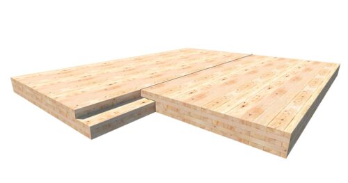
ASSY self-tapping screws are widely used in mass timber applications including lateral connections. Connections using self-tapping screws loaded laterally include but are not limited to CLT butt joint or CLT lap joint connections, beam hanger systems and tension straps . Within these connections, a screw can be loaded in shear or inclined towards the shear plane, where the screw is loaded axially. This blog post will discuss the advantages of using inclined screws in lateral connections and will explain the process of designing these connections through example calculations of a simple wood-to-wood connection using Canadian design codes and the MTC Solutions Structural Screw Catalog.
Approximately 10-minute read.
Lateral connections where screws are loaded in shear are simple to design and assemble, achieving high strengths while remaining ductile. However, it is possible to increase the capacity and the stiffness of a screwed connection by inclining the screws to the shear plane. This can be beneficial in situations where deflection must be limited. By sufficiently inclining the screw towards the shear plane (typically between 30° to 45°), lateral connections can be predominantly characterized by axial effects rather than dowel effects.
Fully threaded screws are optimized for axially loaded configurations and can produce high strengths when used in connections. For example, MEGANT Beam Hanger Systems take advantage of the increased strength and stiffness of inclined screws, reliably pushing the connectors to higher capacities.
The following graph summarizes research at The University of British Columbia demonstrating that a CLT lap joint designed with fasteners inclined at 45° to the shear plane in a screw cross configuration will have significantly higher fastener yield points than a connection designed with screws loaded only in shear (oriented 90° to the shear plane). Additionally, inclined screw configurations provide stiffer connections due to the decrease in elastic deformation. By understanding the behavior of ASSY screws in both inclined and 90° orientation, it is possible to utilize both configurations in combination to create a high capacity connection with a well-defined and predictable ductile region.
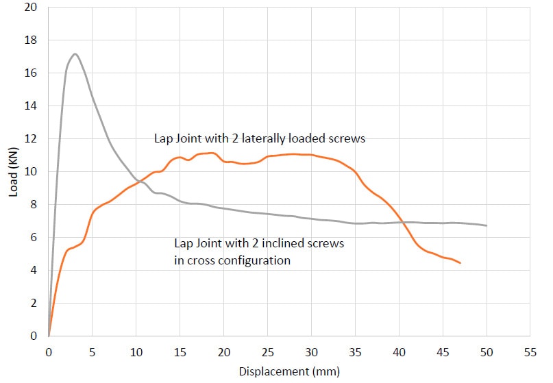
Load Displacement Curves of Lap Joint Connection with ASSY Self-tapping Screws
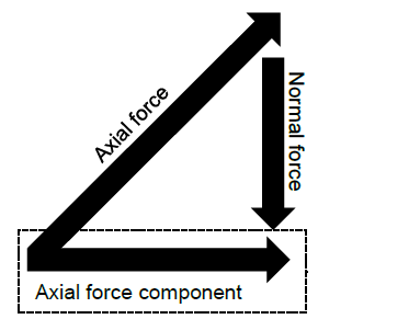
Calculating the design capacity of inclined screw connections is done by utilizing the simplified truss model shown below. The truss model is based on the idea that all design strength can be considered as the product of axial effects only, and that dowel effects can be neglected for the sake of practicality. For more design information on ASSY self-tapping screws, refer to the MTC Solutions Structural Screw Catalog.
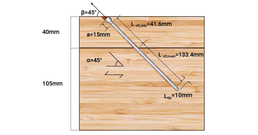
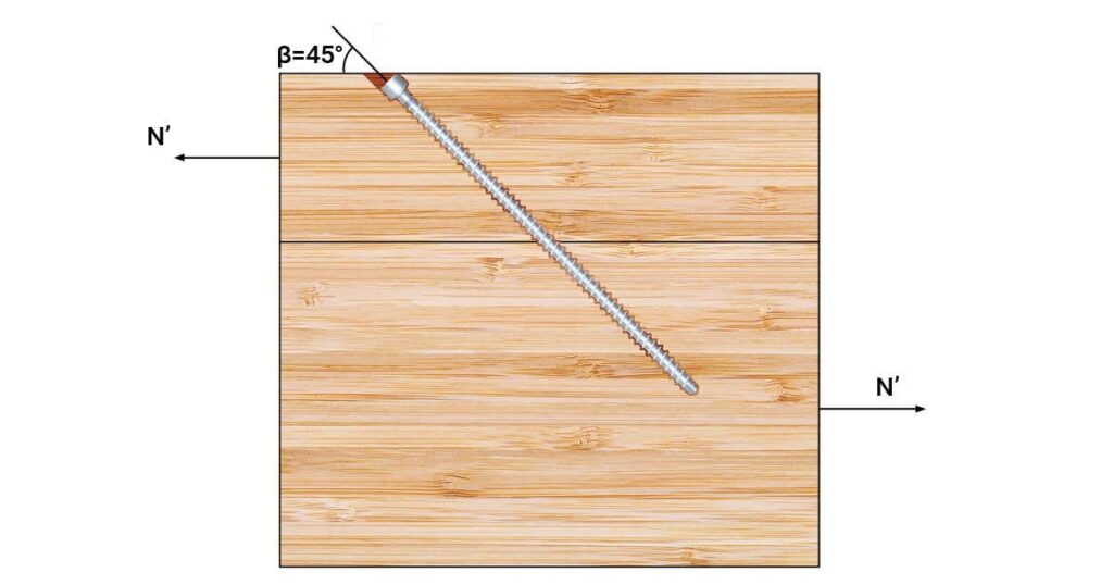
The following example will go through calculations of an inclined axially loaded screw with appropriate geometry requirements placed 45° to the shear plane. The lateral resistance of an inclined fully threaded screw, N′, will be limited by withdrawal in the side member, withdrawal in the main member or screw tensile fracture.
$$\boldsymbol{N′} = \text{Minimum of}\begin{Bmatrix} &\text{Factored withdrawal resistance in side member}& \\ &\text{Factored withdrawal resistance in main member} & \\ &\text{Factored tensile resistance of screw} & \end{Bmatrix}\times \boldsymbol{\cos\beta}$$
Where β is the angle between screw axis and line of the force (30° ≤ β ≤ 45°)
In this example, the following geometry and conditions are considered.
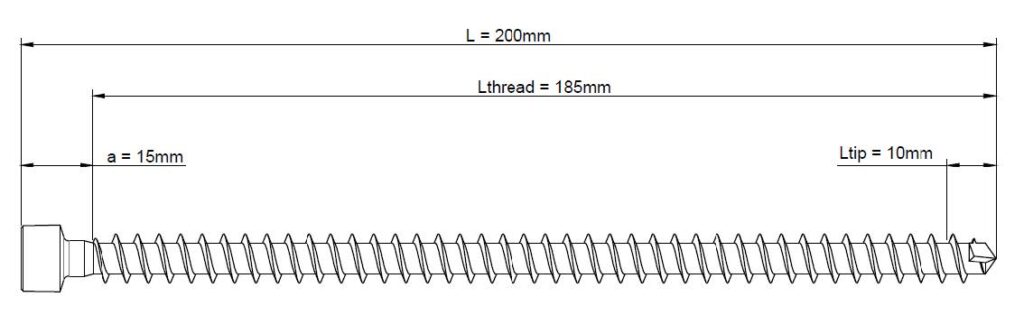
Screw, 1 piece* of ASSY VG Cyl 10 x 200 mm
* Note that a load bearing connection shall consist of at least two 2 screws
Wood material,
Adjustment factors,
1. Total length of screw in the side and main members
First, the total screw length in each wood member is calculated,
$$sin 45° = {40 \over \boldsymbol{L_{side}}}$$
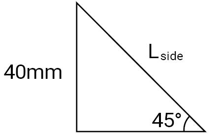
Lside = 56.6 mm, length of screw in the side member including the screw head.
Lmain = 200 − 56.6 = 143.4 mm, screw length in the main member including screw tip.
2. Find the factored withdrawal resistance in side member Prw,α,side
Inclined screws utilize withdrawal capacity. The factored withdrawal resistance calculation in the MTC Solutions Canadian Structural Screw Design Guide can be used with an Angle to Grain Reduction Factor for Withdrawal (R𝛼) equation to account for screw inclination:
Prw,α,side= P’rw,90 ✕ Rα ✕ Leff,side
P’rw,90 = 76 kN/mm, Unit factored withdrawal resistance for withdrawal at an angle α of 90° to the grain for SPF, from the MTC Solutions Canadian Structural Screw Design Guide Table FR.1.1, which includes ∅ = 0.9 and relates to relative densities of specified wood species.
α =45°, representing angle between axis of screw and direction of wood grain (α ≥ 30°). Using MTC Solutions Canadian Structural Screw Design Guide, Table Table FR.1.2, α=45° corresponds to R𝛼 = 0.857. This represents the angle to grain reduction factor for withdrawal, which reduces the withdrawal resistance of self-tapping wood screws according to the insertion angle to the grain orientation.
The effective length of the screw head (a) is subtracted from the total screw length in the side member (Lside) to find the effective screw thread embedment (Leff,side) in the side member:
Leff,side = Lside – a = 56.6 − 15 = 41.6 mm
3. Find the factored withdrawal resistance in main member, Prw,α,main
Calculating withdrawal resistance in the main member follows the same process as with the side member. All variables, except the effective length as we are in the main member, will be equal to the one used in step 2.
Prw,a,main= P’rw,90 ✕ Rα ✕ Leff,main
The effective length of the screw tip (Ltip) is subtracted from the total screw length in the side member (Lmain) to find the effective screw thread embedment (Leff,main) in the main member.
Leff,main = Lmain – Ltip = 143.4 − 10 = 133.4 mm
Prw,a,main = 76 ✕ 0.857 ✕ 133.4 = 8688.6 N = 8.689 kN
4. Find the lateral resistance of a shear-tension screw, N′
Now, compare component capacities as below. Factored tensile resistance of ASSY screws can be found in the MTC Solutions Canadian Structural Screw Design Guide Table FR.3.1.
$$\boldsymbol{N} = \text{Minimum of}\begin{Bmatrix}&\text{Factored withdrawal resistance in side
member}& \\ &\text{Factored withdrawal resistance in main member} & \\ &\text{Factored tensile
resistance of screw} & \end{Bmatrix}\times \boldsymbol{\cos\beta}$$
$$\boldsymbol{N} = \text{Minimum of}\begin{Bmatrix} & P_{rw,a,side} = 2.709kN & \\ & P_{rw,a,main} =
8.689kN & \\ & T_s = 19.20kN & \end{Bmatrix}\times \cos45° = \boldsymbol{1.916}\,\boldsymbol{kN}$$
Therefore, withdrawal resistance of the side member governs.
5. Find connection capacity in shear
The final step is to find the connection capacity in shear by taking a simple component resistance.
Nr = N′ ✕ nF ✕ nR ✕ J’ ✕ K’
Since one screw is used in this example, nF = (n0.9, 0.9n) = 10.9 = 1
For this example, adjustment factors all equal 1, J′ & K′ = 1
Register for a Technical Learning Session
Sign up for MTC Newsletter and keep up to date with all our progress.