MTC Solutions beam hanger systems provide high-capacity connections that add value to building projects by simplifying the design, detailing and installation process. The Beam Hanger Design Guide outlines requirements for connector placement and instructions for installation, and when properly followed, produces the best results for many connection possibilities. That being said, mistakes can happen, and connectors may need to be relocated to its proper location on the timber member.
Approximately 15-minute read.
Equipment and Material List:
The first step in relocating any MTC Solutions beam hanger connector is to use the proper tools:
It is suggested to consult the Beam Hanger Design Guide and MTC’s technical support team prior to the relocation of any MTC Solutions Beam Hanger System.
Step 1:
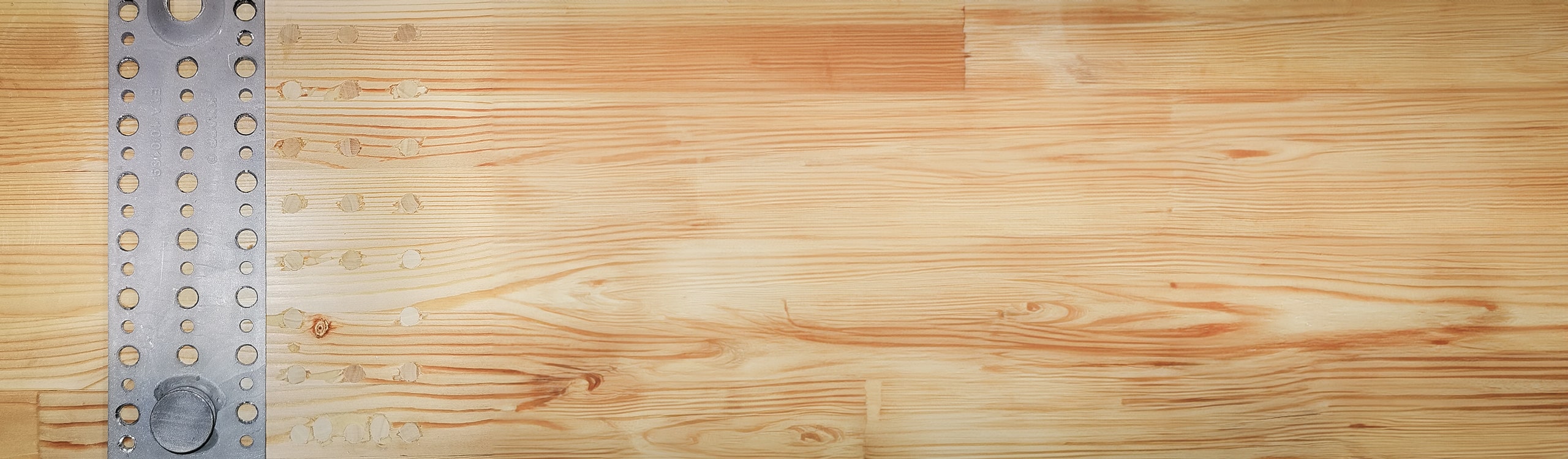
Remove one or both connector plates and screws that were miss installed.
Discard all used screws, new fasteners must be used in the following steps for the relocation.
In certain cases, it may be possible to redesign the connection to adapt to the wrongly placed connector plate rather than relocating it. This may be beneficial when the secondary member connector plate, installed in the end grain, is installed in the wrong position. Relocating connectors in the end grain should always be done with caution as generally the end grain timber is weaker.
If only one connector plate requires relocation, it is suggested to remove and relocate the plate installed in the primary member side grain since there are stronger wood fibers in the side grain to sustain the new dowel installation.
Step 2:
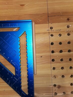
Once the connector plate (or plates) and screws are removed, the screw holes will need to be prepared to accept the 3/8” wooden dowels by drilling to the full embedded length of the removed screws. For this process, a 13/32” [10.3mm] bit must be used. This small difference in diameter ensures a tight installation of the dowel and will allow some space for the wood glue.
As explained in more detail in the next step, smooth dowels and Type 2 wood glue will be installed in these holes to support the beam member for the relocation of the connector to the correct position.
Step 3:
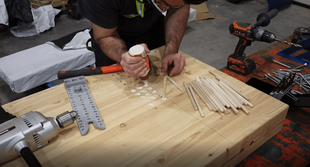
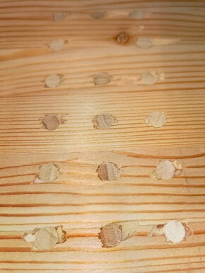
Fill 1/3 of the hole depth with Standard Type 2 wood glue (structural, waterproof preferred). Drive wooden dowels into each hole as deep as possible using a mallet. Hammering the dowels in, forces the glue out of the cavity and surrounds the remainder of the dowel completely with glue. The excess glue should be left to dry for easy removal with a small saw or chisel in the next step.
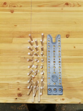
In this scenario, further documented in the accompanying video, the RICON XL 390×80 connector plate was installed too high in the primary member. To reposition lower in the member, all holes were filled with dowels including the two inclined screw holes. Depending on your relocation situation, the number or location of holes to be filled with dowels may vary and should be discussed prior to starting this process.
In this solution, the added dowel material acts as a support preventing the surrounding wood fibers from collapsing once the new fasteners are installed and loaded in shear or withdrawal. The dowels must be sized to provide a tight fit in the drilled holes (for the relocation of the RICON XL 390×80 connector, dowels with a 3/8” [10mm] diameter were used). The dowels should ideally be of the same species as the beam element. Dowels with species of fir, beech or hemlock could also be used. The dowels must be long enough to fill in at least 90% of the length of the drilled holes.
When the glue has set after approximately two hours, cut down the dowels to the glulam surface and smooth the surface to allow for a flush reinstallation of the beam hanger plate.
Using small self-tapping Ecofast screws (outlined in red in Figure 5), level and position the RICON XL 390×80 connector plate to its final correct location. The small Ecofast screws keep the connector in the correct position while the load bearing screws are installed.
Consult the MTC Solutions Beam Hanger Design Guide for proper connector positioning and geometry requirements. Before the installation of the new fasteners, the wood member must be pre-drilled. For 5/16″ [8mm] screws, a 3/16″ drill bit must be used. For 3/8″ [10mm] screws, a 15/64″ drill bit must be used.
The new fasteners should be at least 50% longer than the original screws. For relocating the RICON XL 390×80 connector, ASSY VG CSK 3/8” x 11-7/8” [10x300mm] screws are recommended to penetrate and engage more wood material.
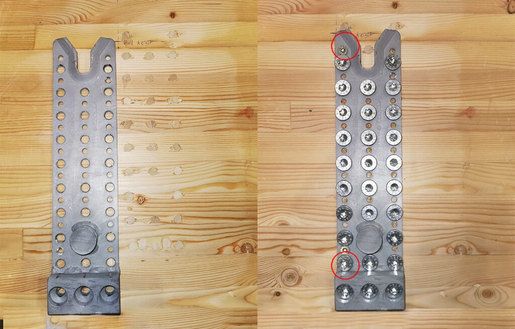
Figure 5 Reinstallation of RICON XL 390×80 Plate
Step 6:
In the final step to prevent potential perpendicular to grain splitting, it is recommended to install reinforcing screws in the primary or secondary beam members. For a complete explanation of reinforcing screw installation solutions for the beam hanger systems, refer to the MTC Solutions Beam Hanger Design Guide or contact our technical support team.
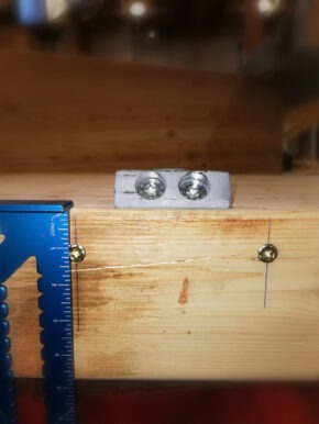
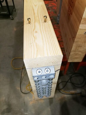
Figure 7 Example Reinforcement of Secondary Member (If required)
This blog post provides general recommendations for the relocation of the RICON XL 390×80 beam hanger connector after one or both connector plates are miss-installed. The solutions detailed in this blog post should not be applied to all project types and may depend on other project-specific factors. It is highly recommended to contact our technical support team prior to removing any beam hanger connectors that were installed in the incorrect position. Our team of experienced engineers can provide proper guidance on the best course of action for your specific project.
Register for a Technical Learning Session
Sign up for MTC Newsletter and keep up to date with all our progress.