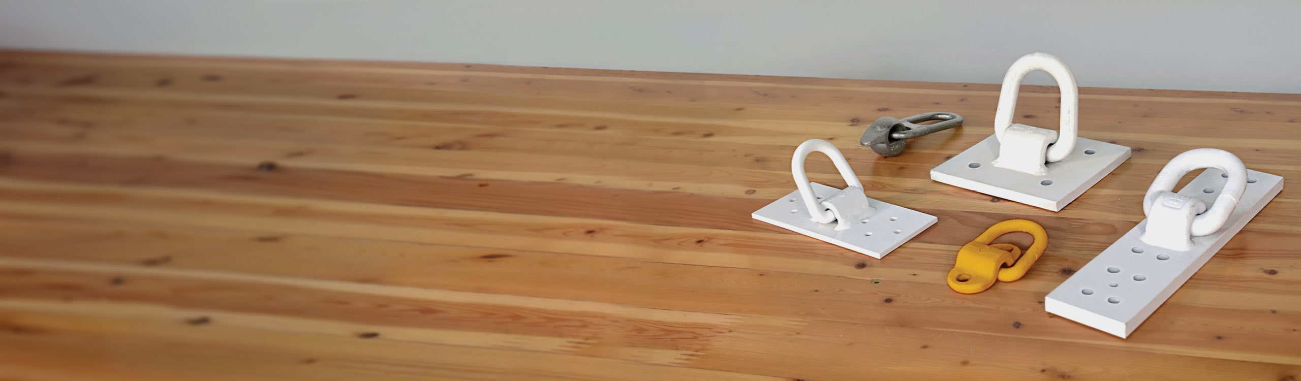
MTC Solutions offers a variety of innovative rigging systems designed for efficient and safe rigging of mass timber elements. Installed with our high-performance, code-compliant ASSY self-tapping screws (STSs), these anchors meet, among others, OSHA, AMSE, and IHSA safety standards in the United States and Canada for hoisting and rigging products, incorporating proper factors of safety. These rigging solutions have been instrumental in the success of several prominent mass timber landmarks across North America.
In this article, we’ll break down the process on how to best select the rigging devices you need, and how to work with us (and your licensed rigging professional), for a reliable, safe and efficient lifting process.
Approximately 8-minute reading time.
Commonly Rigged Structural Wood Elements
The most common structural wood elements that require hoisting on construction sites are:
To meet different rigging needs, MTC Solutions distributes five distinct anchoring systems:
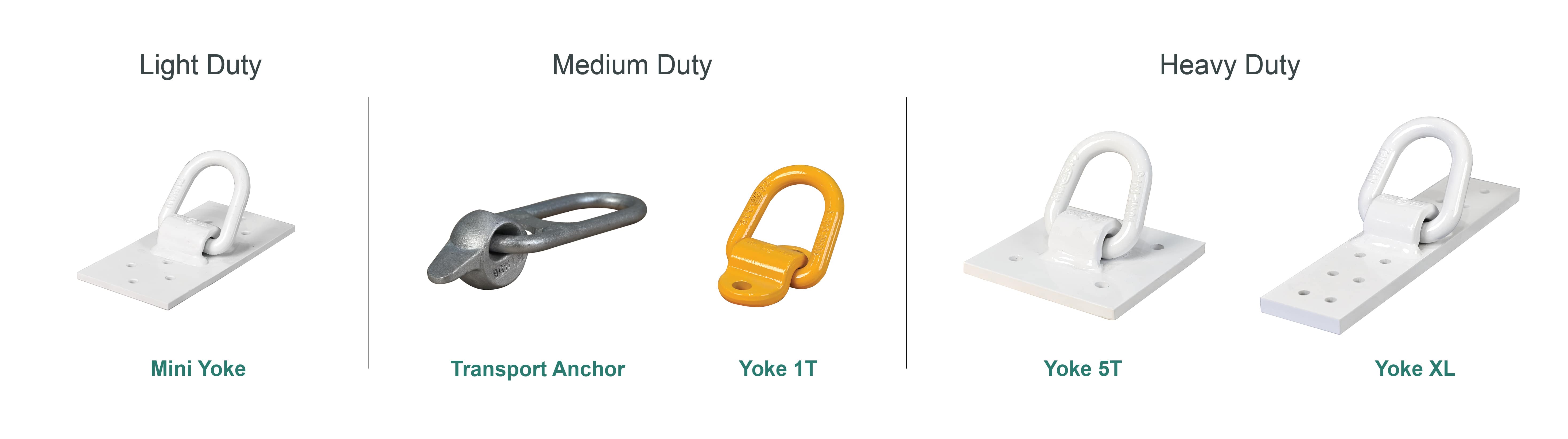
Figure 1. Visual overview of MTC Solutions’ rigging systems categorized by duty rating
These anchors are installed onto wood members with a selected range of ASSY self-tapping screws (STSs), chosen to ensure that no predrilling is required for installation in any wood species, including Douglas Fir (DF) and Southern Yellow Pine (SYP). These high-performance, code-compliant STSs significantly enhance on-site efficiency.
Choosing the Right Rigging Device for Your Needs?
Once you have determined the total factored load to be lifted, it is time to choose the appropriate rigging device. It is also important to select the right number of anchors to be used to lift structural elements, which depends on multiple factors, including, but not limited to, their type, weight, and dimensions, as well as the type of crane used.
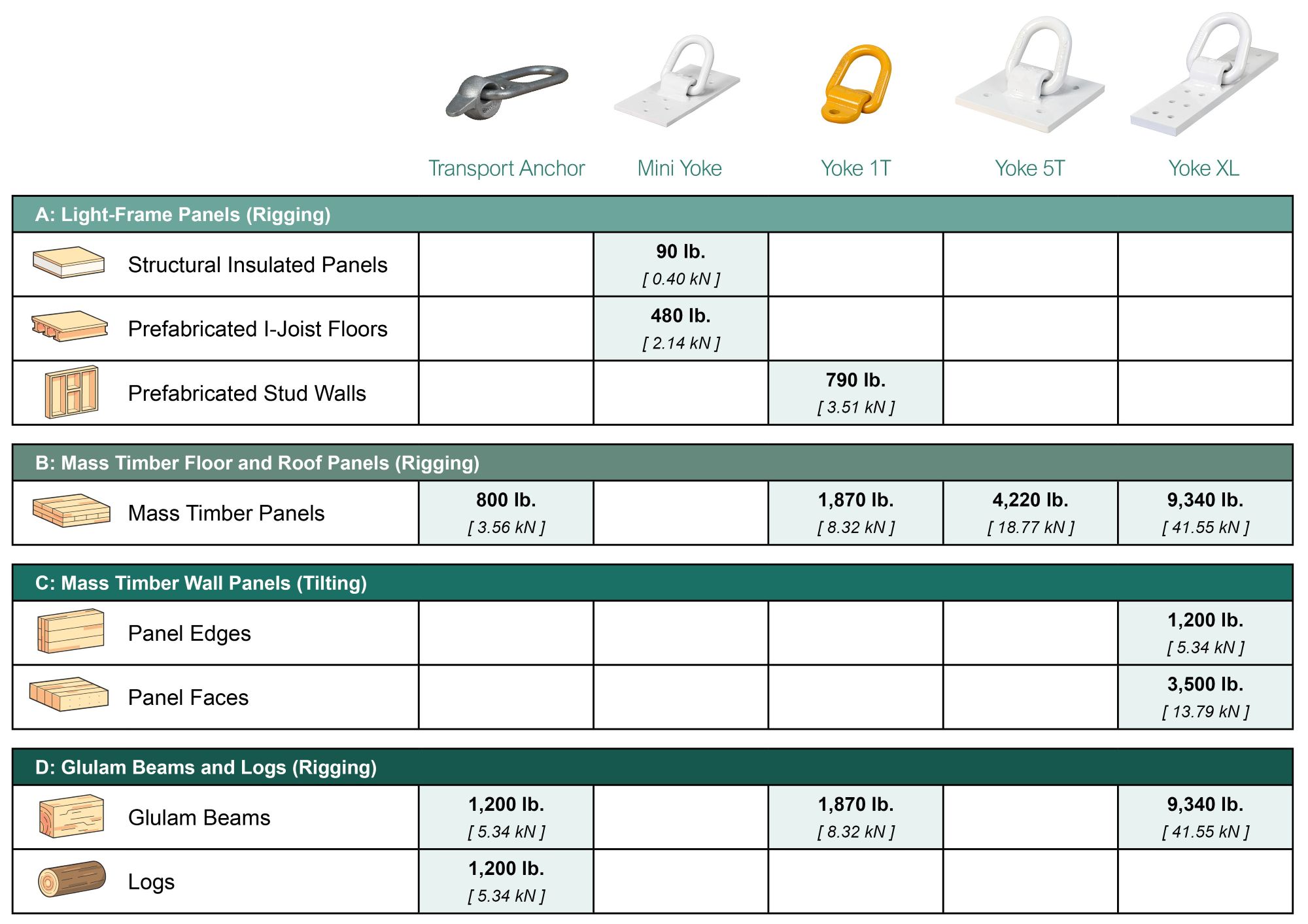
Figure 2. Suggested rigging capacities (factored) by product and applications
Disclaimer: All values presented in the table above are the maximum factored capacity per anchor used while rigging and do not indicate the maximum weight of structural wood members that can be lifted.
Load Distribution Considerations
Two anchors are commonly used to tilt up CLT wall panels, while lifting floor or roof panels generally requires four anchors. In scenarios involving more than two anchors, accurately determining the load on each anchor can become challenging due to the uncertainties associated with the symmetry of load distribution, which impacts the number of anchors in effect. To calculate the load capacity of an anchor assembly (a hitch) and ensure on-site safety, please refer to your licensed rigging professional.
Calculating Anchor Demand and Capacity
Our Rigging Design Guide provides a straightforward procedure to calculate the demand on each anchor, as well as the capacity of the anchor. The demand on each anchor depends not only on the weight of the object being lifted, but also on specific site conditions including crane types, whether the rigging space is open or tight, and the sling angle.
First, you must determine the total force per anchor, 𝑭, in an assembly of multiple anchors using the following equation.

Equation 1. Calculating anchor demand
Where,
Then, to determine the appropriate product to resist the demand, you’ll have to calculate the adjusted anchor capacity, 𝒁’.

Equation 2. Calculating adjusted anchor capacity
Where,
To help this design process, we have added an annex at the end of this article with two examples of how to calculate anchor demand and capacities for different assemblies.
How to Work with Us on Your Rigging Plan?
At MTC Solutions, we provide top-notch technical support to help you choose the right tools for your projects, and here is how it works.
Interested in learning how to install these products safely? Check out our YouTube channel playlist on rigging, covering all details you need to know!
For detailed rigging options and lifting guidance, download the MTC Solutions 📖 Rigging Design Guide and for any questions or help with rigging plans, contact our Technical Support Team 😉
The following annex section of the blog article covers two examples of how to calculate anchor demand and capacities for different assemblies. For the following examples, the following assumptions have been made:
Example 1: Lifting CLT Floor Panels
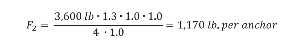
Using Eq. 1 and the assumptions above, the force per anchor for two separate CLT floor panels (t ≥ 7.5 in., G = 0.50) can be determined: Panel One weighing 28,000 lb. (p1) and Panel Two weighing 3,600 lb. (p2). Each panel will be lifted individually using four anchors (𝑛 = 4).
Panel One:
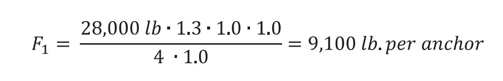
The anchor capacity is determined by using Eq. 2. As the sling angle is equal to 60°, 𝑅𝐴𝑅 = 1.0, and assuming the lift will take less than 10 minutes, 𝑅𝐷 = 1.0. For these conditions, 𝑍’ = 𝑍 ⋅ 1.0 ⋅ 1.0, so the tabulated reference capacity per anchor, 𝑍, is equal to the adjusted capacity, 𝑍’.
Table 3.7, “Reference Rigging Capacity (Z) of the Yoke XL for Rigging Flat CLT Panels”, in the Rigging Design Guide lists the reference capacity per anchor, 𝑍, of a Yoke XL using 12 VG CSK 3/8” x 6-¼” [ 10 mm x 160 mm ] screws as 9,340 lb. This meets the demand for Panel One.
Having multiple rigging devices on site can be challenging, which is why Yoke XL’s flexibility is ideal for jobsites that need to move panels of varying weights. The Yoke XL can be used to meet the demand for Panel Two simply by using fewer screws. Four VG CSK 3/8” x 6-¼” [ 10 mm x 160 mm ] provide sufficient capacity at 3,110 lb per. anchor. Engineers should always ensure that required minimum penetrations are met, and for CLT panels, that a minimum of three laminations are engaged by the fasteners.
Example 2: Lifting Prefabricated Light-Frame Stud Walls
Prefabricated light-frame stud walls are commonly lifted using two anchors (𝑛 = 2); therefore, 𝑅𝐿𝑆 = 1.0. The Yoke 1T is the recommended anchor for stud walls with double top plates, employing two VG CSK 3/8” x 4” [ 10 mm x 100 mm ] screws for each anchor. For this example, the wall weight, 𝑝, is assumed to be 1,200 lb.
Following the previous assumptions with respect to crane type, rigging conditions, and sling angle, the force per anchor, 𝐹, can be calculated using Eq. 1 from the Rigging Guide:

As before, Eq. 2 in the Rigging Design Guide simplifies 𝑍’ = 𝑍 for the assumed conditions (i.e., the tabulated reference capacity per anchor, 𝑍, is equal to the adjusted capacity, 𝑍’).
Table 3.2, “Reference Rigging Capacity (Z) of the Yoke 1T for Rigging Double Top Plate Stud Walls”, in the Rigging Design Guide shows the capacities for Yoke 1T anchors in double top plate stud walls. The reference rigging capacity, and therefore adjusted capacity, is 790 lb., exceeding the demand of 780 lb. per anchor.
Register for a Technical Learning Session
Sign up for MTC Newsletter and keep up to date with all our progress.