Published beam hanger capacities are not simply the highest load recorded during testing. Recognized design standards and acceptance criteria define how full-scale test results must be generated, interpreted, and converted into published design values that engineers can directly apply.
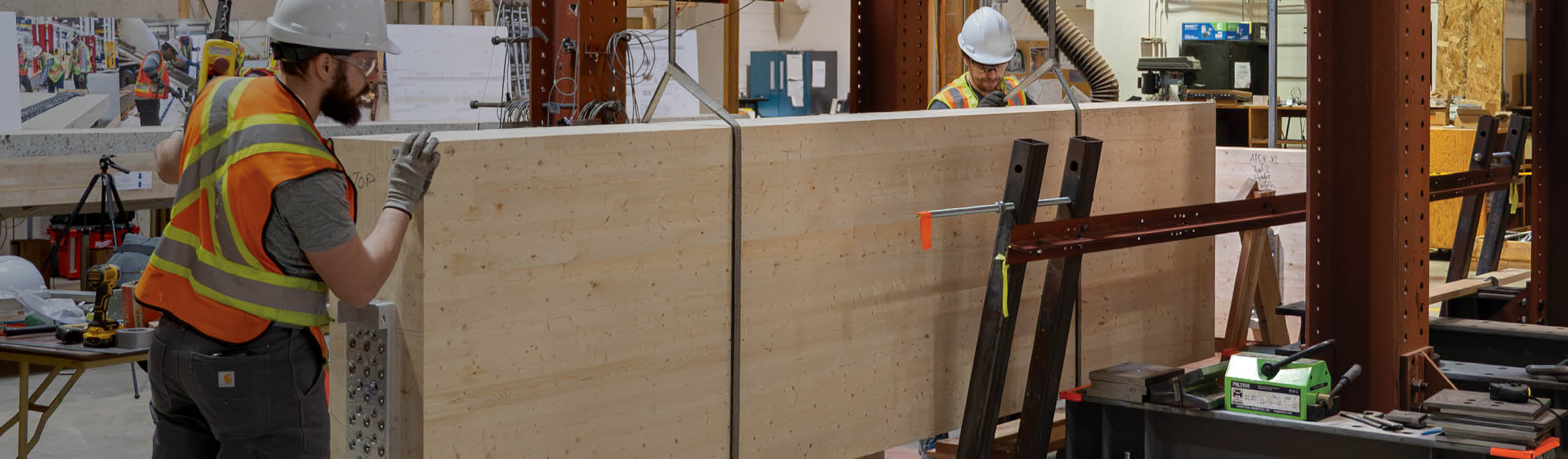
The development of the APEX beam hanger system provides a clear example of this process. Beyond demonstrating strength, it required the creation—from the ground up—of a structured full-scale testing program, supporting material characterization, and formal interpretation under recognized design standards.
This article highlights key considerations for structural engineers when reviewing and using published capacities from mass timber hardware suppliers. In a hurry, we want you to remember that not all published capacities are the same!
Using the APEX development journey as a reference, we explain how full-scale downward testing of beam hangers is conducted in North America and how the resulting data are converted into allowable loads (ASD) in the United States and factored resistances (LSD) in Canada. We also cover important considerations when using and interpreting European data issued under ETAs, as well as supporting material and fastener testing.
8-minute read.
Why Does Testing Rigor Matter for Beam Hanger Capacities?
Developing connection solutions specifically designed for mass timber and wood structure introduce sources of variability that are not present in steel or concrete systems. Wood fibre can fail in brittle modes, fastener combinations can alter load paths, and connection geometry can shift the governing failure mechanism.
In high-capacity concealed connections, like the APEX, it is not always possible to predict whether failure will be governed by fasteners, wood fibre rupture, localized wood crushing, or connector deformation without full-scale evaluation. Therefore, design standards address this uncertainty through:
These provisions normalize material variability and manufacturing tolerances while preserving the safety margins required by the governing design standard. Without full-scale validation, brittle wood failure modes and system-level interactions may not be captured by component-level calculations alone.
But how? Let’s dive in!
1. Brittle Wood Failure and System Effects
Wood does not fail in a single predictable mode.
Depending on fastener orientation, spacing, edge distance, and load level, connections may experience localized fibre rupture, plug shear, splitting, or other brittle mechanisms. These behaviours are influenced by the interaction between fasteners and wood fibre and are not fully captured by simplified fastener equations.
Full-scale testing confirms which component governs and ensures that brittle wood failure modes are reflected in the published resistance.
2. Full-Scale Download Testing per ASTM D7147
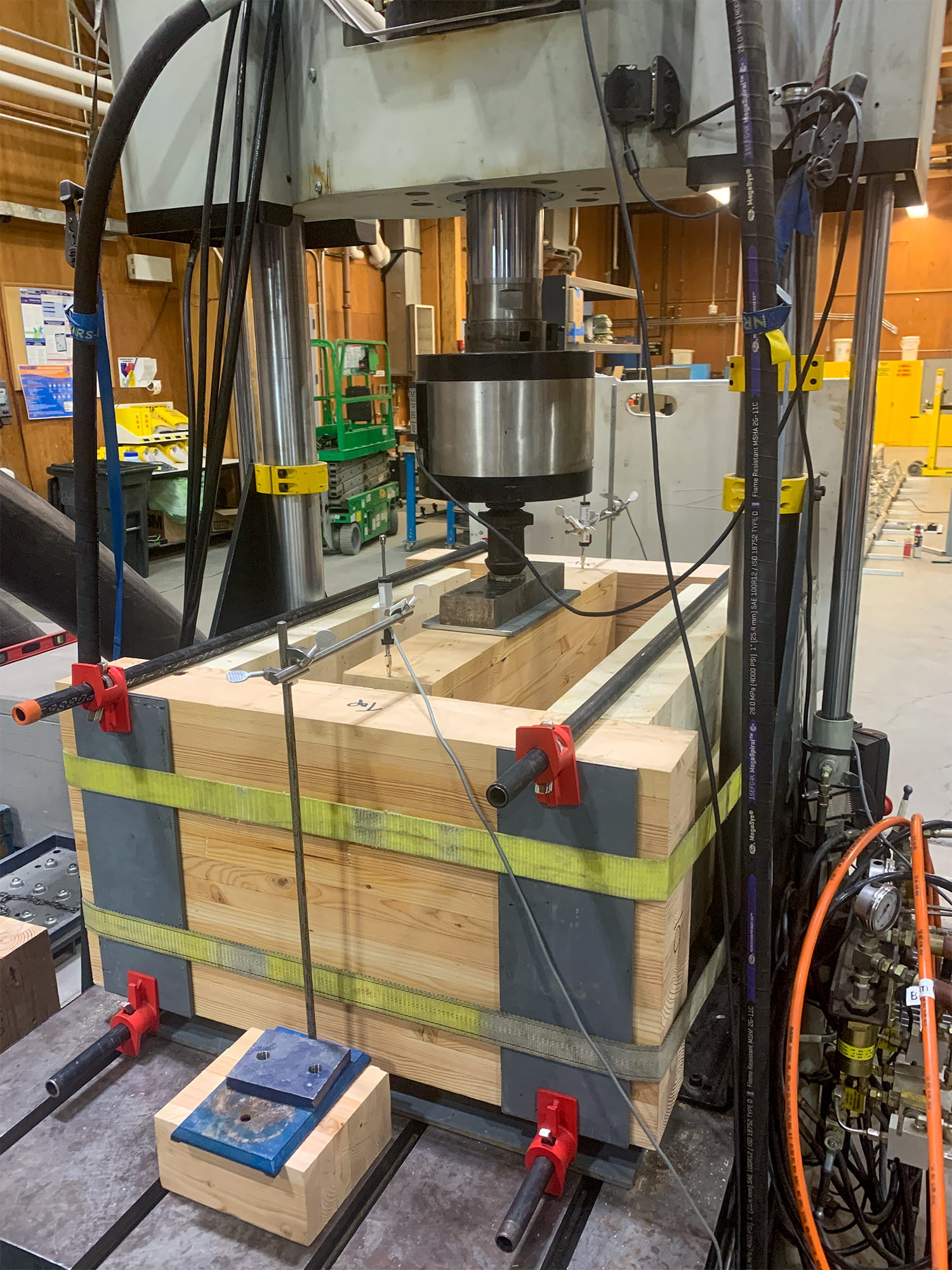
Figure 1. Full-Scale Connector Testing per ASTM D7147
Beam hanger models evaluated under AC13 and CSA O86:24 require full-scale ultimate download testing in accordance with ASTM D7147. Testing follows a prescribed three-member configuration, with load applied uniformly to two connectors to promote realistic boundary conditions rather than isolated fastener response.
Because timber introduces inherent material variability, repeatability is a critical component of resistance derivation under both AC13 and CSA O86:24. Consistent full-scale behaviour provides confidence that published values reflect predictable system performance rather than isolated test outcomes. Representative testing demonstrated consistent peak loads, with coefficients of variation (COV) within expected ranges for structural timber connections (see Figure 2).
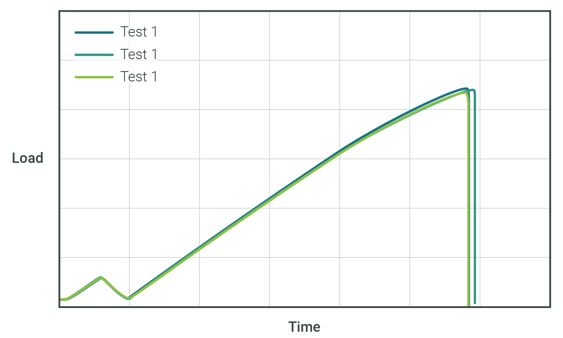
Figure2. Example Load vs. Time from APEX Testing
Once repeatable behaviour has been established through testing, the next step is interpreting those results within the framework of the governing design standards in the United States, per AC13, in Canada, per CSA O86:24, and in Europe, per the ETA. These standards define how test outcomes are converted into the published capacities. How do they differentiate?
AC13 is the ICC-ES acceptance criteria commonly used to evaluate hanger and connector performance for code compliance under the International Building Code (IBC). Under this acceptance criteria, allowable loads are governed by the minimum of three checks:
Ultimate load alone does not define the allowable load; it is only one component of the evaluation.
Factored Resistances per CSA O86:24 in Canada
In Canada, factored resistances for joist hangers are established in accordance with CSA O86:24 Clause 17.5.
To derive a resistance directly from testing, a minimum of three full-scale tests per connector configuration are required. The ultimate test loads are used to establish a corrected ultimate load per hanger in accordance with Clause 17.5. The governing load may be controlled either by ultimate strength or by the deformation limits prescribed within the standard. The corrected ultimate load is then multiplied by the prescribed resistance factor to obtain the factored resistance.
Where full-scale testing in accordance with ASTM D7147 is not performed, resistances must instead be derived from calculated component capacities based on fastener equations and material properties, which tend to be more conservative.
Considerations when Interpreting European ETA Data
Lastly, European Technical Assessments (ETAs) are developed under Eurocode-based partial-factor design, where characteristic resistances are converted to design values using material partial factors and, for timber-related failure modes, modification factors. Because this framework differs significantly from North American acceptance criteria and design standards, ETA capacities cannot be directly converted into Canadian LSD or U.S. ASD values without re-evaluation under the governing standard.
As an example, the effective material reduction implied by partial-factor design for metal components can be on the order of ~0.8–0.9 of ultimate strength in some cases, whereas CSA O86:24 beam hanger resistances are derived by applying a resistance factor of 0.6 to a corrected ultimate load. Differences in test interpretation and governing limit states can therefore produce materially different published capacities for the same physical connector.
For a more detailed comparison between these design standards, read our blog post on the topic that helps navigating values in mass timber connections.
Finally, all full-scale download testing must be supported by additional material testing to ensure compliance with both AC13 and CSA O86:24, including:
Material normalization is not trivial. In representative cases, accounting for measured overstrength in fasteners and connector materials can reduce the governing ultimate load by 20% or more before allowable loads or factored resistances are established — a meaningful adjustment that directly preserves the safety margins intended by the governing standard.
As stated initially, not all published capacities are established using the same level of full-scale validation.
When reviewing published connector capacities, it is reasonable to ask yourself:
Understanding how a value was established provides confidence that it reflects verified system behaviour under recognized standards. For high-capacity connections, where brittle failure modes and material variability are real, that understanding matters.
And as usual, if you have a doubt, a question or want to learn more, we cannot recommend enough to get in touch with the mass timber hardware specialist 😉 Contact our Technical Support Team here, we are ready to assist.
Register for a Technical Learning Session
Sign up for MTC Newsletter and keep up to date with all our progress.