MTC Solutions design guides provide essential connection detailing requirements that ensure safe stress transmittance while minimizing the risk of wood splitting. This two-part technical blog series, titled “Geometry Requirements for Structural Screws,” addresses key questions regarding connection geometry requirements when designing with ASSY® self-tapping screws (STSs).
Part 1 covers fundamental elements, including spacing, end-distance, and edge-distance requirements. This part explores the specifics of these requirements, load directions, and the wedge effect. Additionally, it distinguishes between connection detailing for fully and partially threaded screws. Furthermore, this part also presents a practical approach to assist designers in navigating varying geometry requirements across different resources.
Part 2 delves deeper into the geometry considerations for screwed connections involving structural elements constructed from cross-laminated timber and Douglas-fir. It also addresses specific detailing considerations for connections facilitated by axially loaded inclined STSs.
Approximately 8-minute read.
Geometry Requirements for Cross-laminated Timber (CLT) Connections
CLT represents an engineered mass timber product that comprises multiple layers of lumber boards, each oriented perpendicular to its adjacent layers. These layers are bonded with structural adhesives and pressed to form exceptionally rigid and strong panels capable of withstanding heavy structural loads. The cross-laminated structure, achieved by stacking layers of wood grain in this fashion, enables fasteners installed in CLT to distribute forces along both the strong and weak axes of the constituent lumber boards. This feature effectively counters the wood’s natural tendency to split and is reflected in the geometry requirements for self-tapping screws (STSs) for use in CLT connections in the MTC Solutions Structural Screw Catalog.
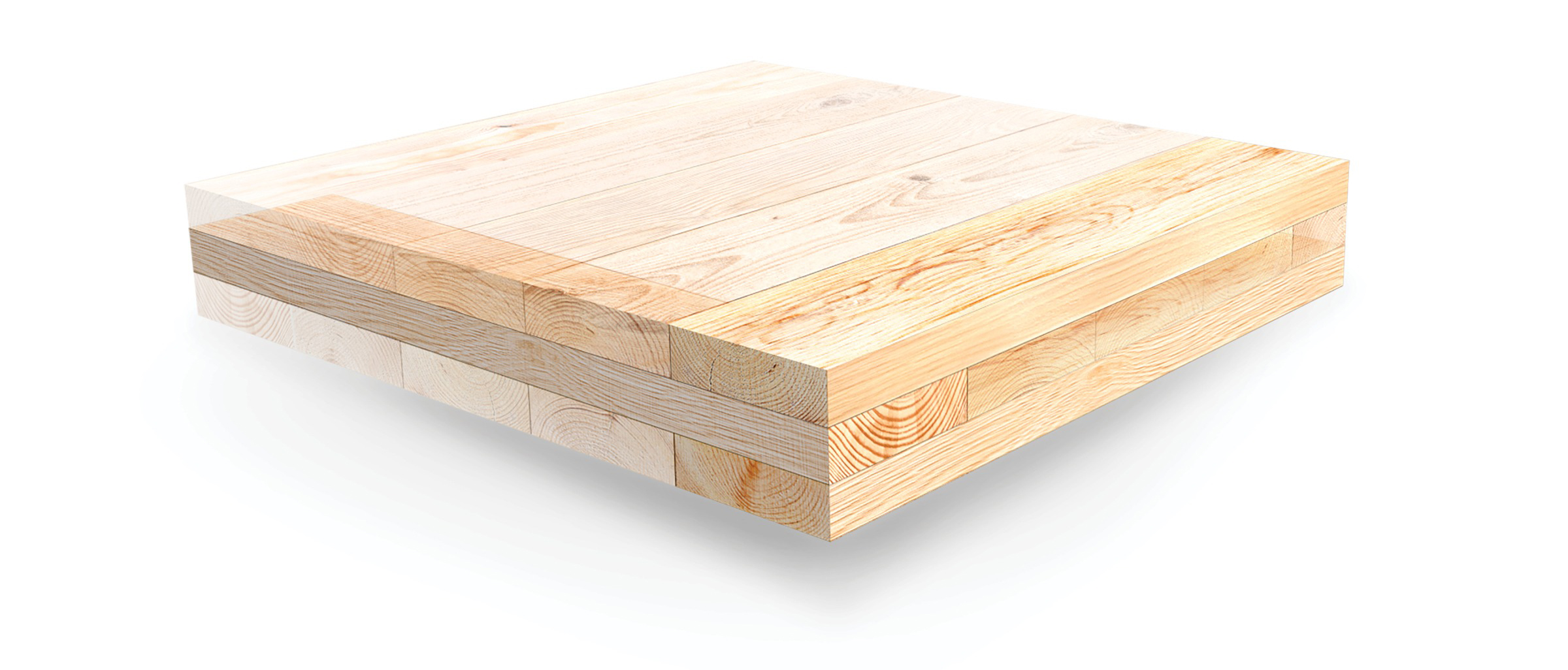
While North American design codes do not specifically prescribe design calculations and checks for wood-related failures in CLT, testing conducted by MTC Solutions suggests that wood-related resistances should be checked when designing with CLT materials.
Geometry Requirements for Douglas-fir Connections
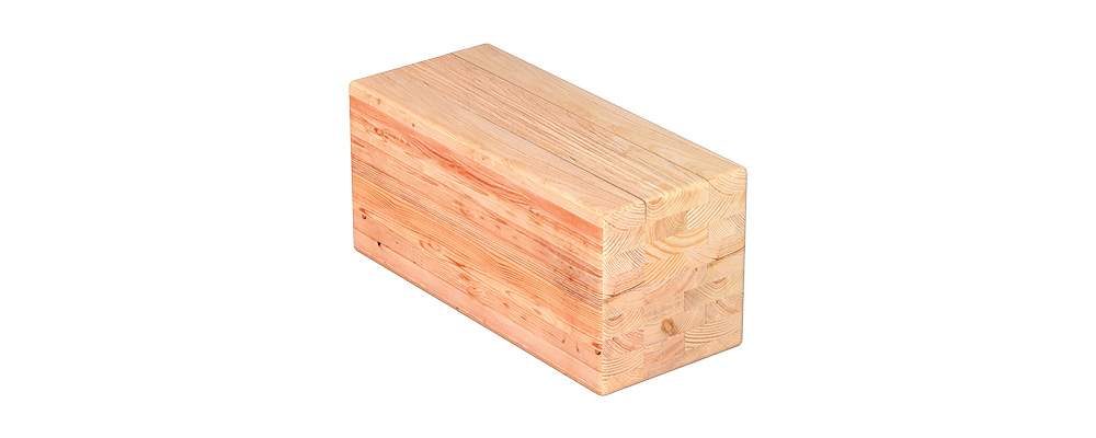
Connections involving Douglas-fir-based timber products necessitate considerably larger geometry requirements compared to those made from other timber species with similar densities. This difference is reflected in the MTC Solutions Structural Screw Catalog.
Specifically, apart from the stipulations outlined in Section 8 of Eurocode 5, an additional provision specified in the ETA-11/0190 for ASSY STSs is applied to the geometry requirements for Douglas-fir connections. This entails a mandated 50% increase in spacings and distances parallel to the grain, affecting both end distance and spacing of fasteners in a row.
Geometry Requirements for Connections Involving Inclined Screws
When detailing the spacings between screws installed perpendicular to the surface of a timber element, a simple measurement between screw heads is adequate to ensure that the geometry requirements provided in the MTC Solutions Structural Screw Catalog are satisfied. However, for screws installed at inclinations between 30° and 45°, a different approach is warranted. In these cases, where the screws are inclined to the shear plane, they are axially loaded, necessitating adherence to geometry requirements corresponding to axial loading.
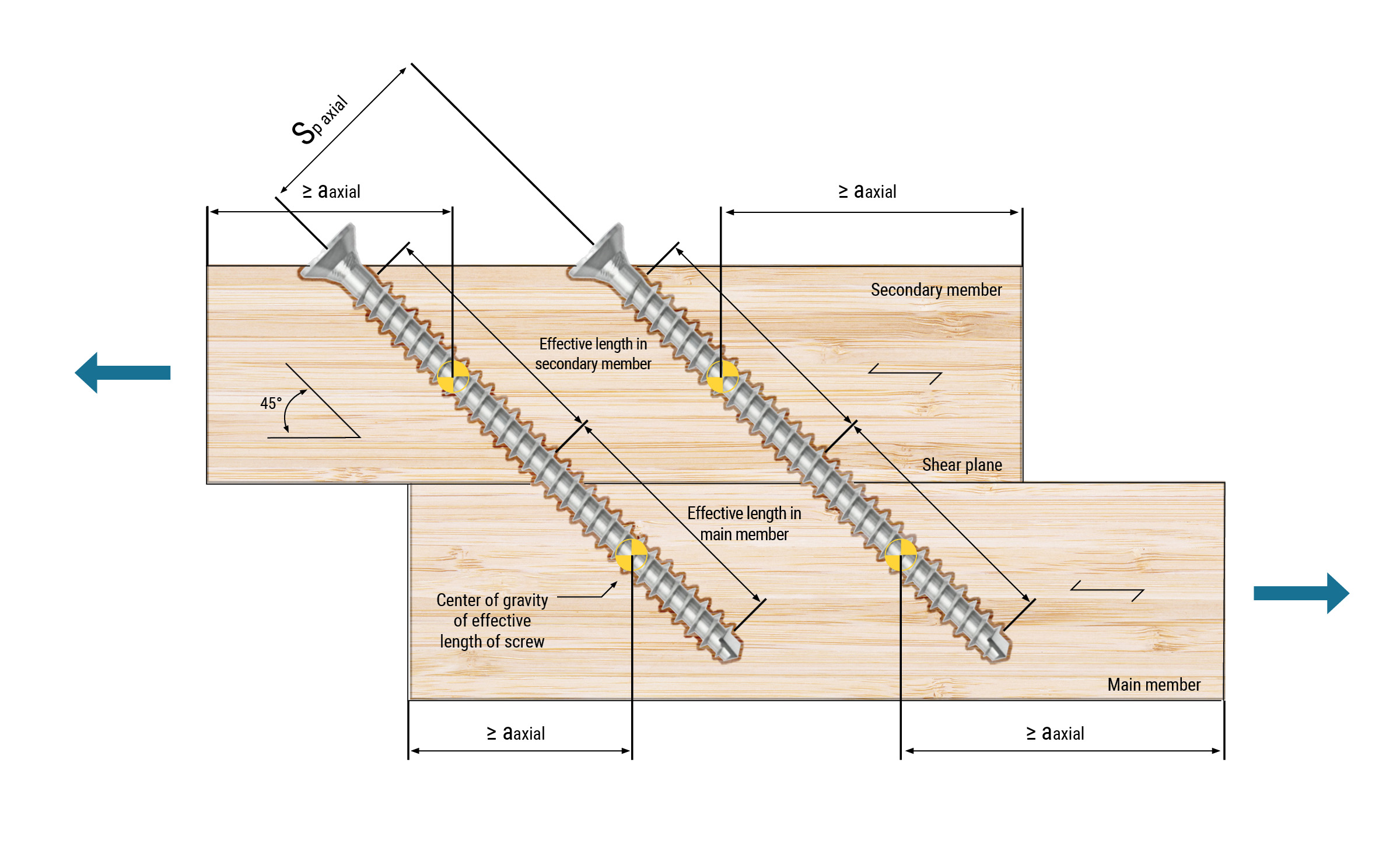
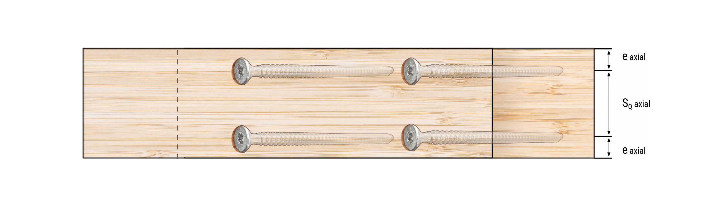
First, for connections with inclined screws, the spacing between fasteners in a row, Sp axial, is measured perpendicular to the axis of the screw, as shown in Figure 3, resulting in a larger spacing measurement projected onto the surface of the element.
Second, the end distance, aaxial, is determined from the center of gravity of the effective screw length in each member. In practice, this is calculated as the midpoint of the penetrating screw length, excluding the effective tip and head lengths in each member. The spacing requirements in the direction across the grain (i.e., edge distance and spacing between rows of fasteners) are measured in the same way as in regular 90° installations.
Method for Determining Geometry Requirements
The methodology provided by the European Organization for Technical Assessment (EOTA) currently stands as the sole available approach for establishing minimum spacings, end distances, and edge distances for STSs.
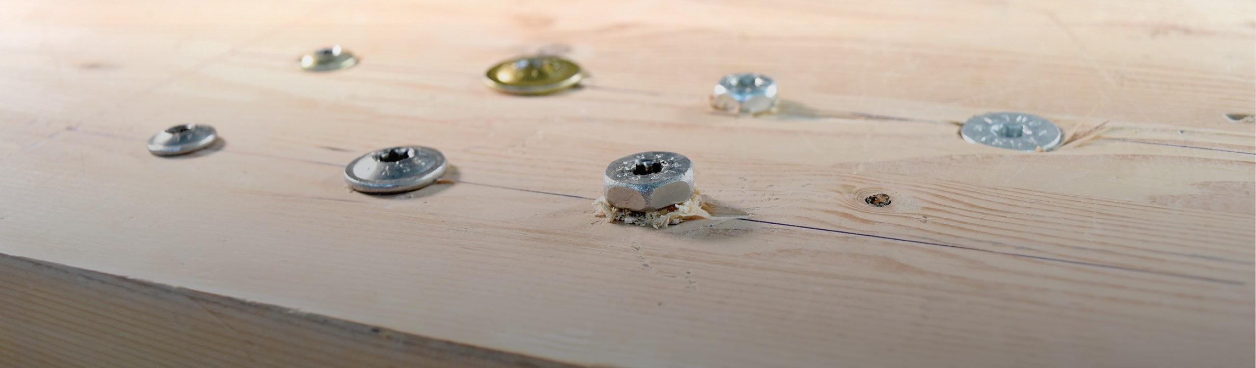
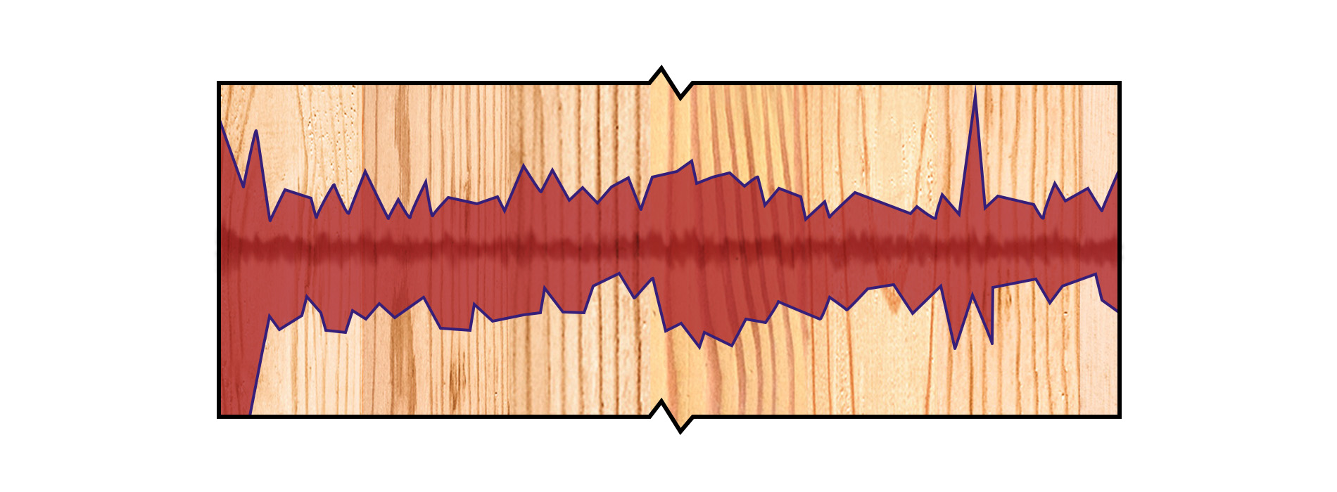
In brief, the process involves initially driving screws into wood specimens perpendicular to the grain, followed by their extraction. Subsequently, a low-viscosity dye is injected into the holes created during insertion and extraction, which permeates the screw-split areas through capillary action. The wood specimens are then opened along the split surface, exposing the dyed areas for measurement, as illustrated in Figure 5. If the dimensions of the split areas meet specific conditions, then the spacing, end distance, and edge distance used in the test are considered the minimum geometry requirements for the examined screws and timber species.
Notably, this approach accounts for a crucial factor—the internal splitting of wood induced by both the insertion moment and the specific tip and thread geometry of the screws. As of the publication date of this article, this method is primarily employed in Europe, with limited application elsewhere, particularly in North America. The geometry requirements provided in other jurisdictions are generally conservative estimates, potentially lacking validation through testing and analysis.
Part 2 of this blog post series provides special detailing considerations for CLT and Douglas-fir connections as well as connections with axially loaded inclined STSs. For background information on geometry requirements and details regarding the differences between fully and partially threaded fasteners, please refer to Part 1 of the series.
Our Structural Screw Catalog offers detailed instructions and considerations on designing connections with STSs. For more information and design guidance, please contact our Technical Support Team. 🙂
Register for a Technical Learning Session
Sign up for MTC Newsletter and keep up to date with all our progress.