MTC Solutions design guides provide essential connection detailing requirements that ensure safe stress transmittance while minimizing the risk of wood splitting. This two-part technical blog post series, titled “Geometry Requirements for Structural Screws,” addresses key questions regarding connection geometry requirements when designing with ASSY® self-tapping screws (STSs).
Part 1 covers fundamental elements, including spacing, end-distance, and edge-distance requirements. This part explores the specifics of these requirements, load directions, and the wedge effect. Additionally, it distinguishes between connection detailing for fully and partially threaded screws. Furthermore, this part also presents a practical approach to assist designers in navigating varying geometry requirements across different resources.
Part 2 delves deeper into the geometry considerations for screwed connections involving structural elements constructed from cross-laminated timber and Douglas-fir. It also addresses specific detailing considerations for connections facilitated by axially loaded inclined STSs.
Approximately 8-minute read.
Spacing, End-Distance, and Edge-Distance Requirements
Geometry requirements serve as the backbone for ensuring the safe and efficient transfer of forces between structural wood elements and ASSY® self-tapping screws (STSs). These requirements, rooted in a tested understanding of wood materials, are mandated by Code Approvals from the International Code Council (ICC) and the Canadian Construction Materials Centre (CCMC) in the United States and Canada, respectively. They generally align with the geometry requirements outlined in manufacturer-specific European Technical Assessments (ETAs) for STSs that do not require predrilling.
The spacing, end-distance, and edge-distance requirements, as defined below, establish the minimum specifications for the placement of STSs supplied by MTC Solutions:
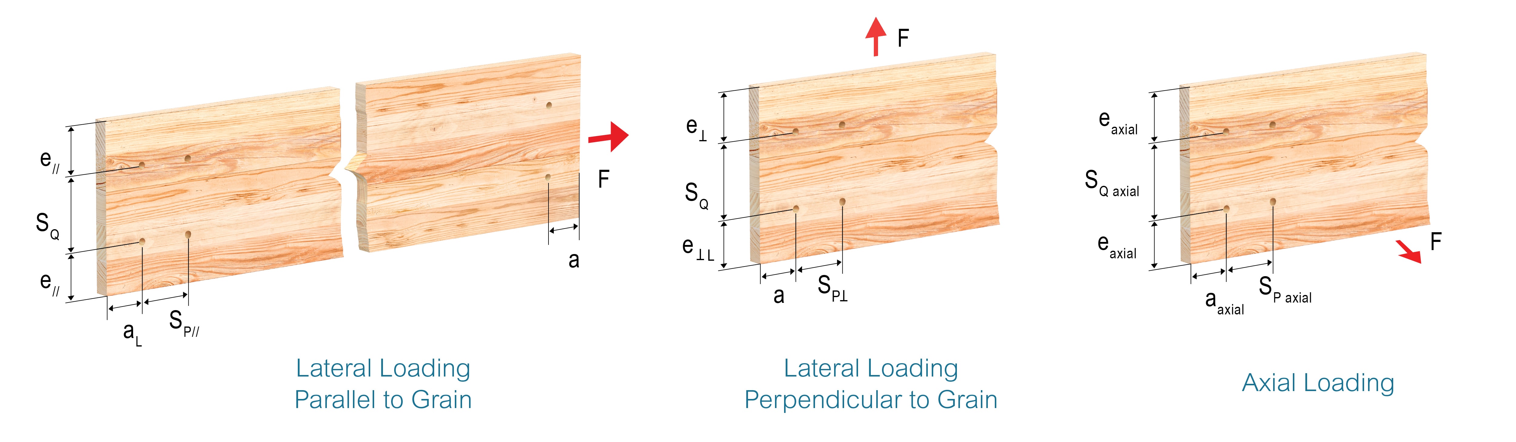
The geometry requirements vary depending on the angle at which force is applied relative to the direction of wood grain. They are tabulated as linear functions of the fastener diameter (D). These requirements work in tandem to ensure the safe transfer of forces and to mitigate the risk of wood splitting. For further details, please refer to the MTC Solutions Structural Screw Catalog.
Basics of Wood Material Structure
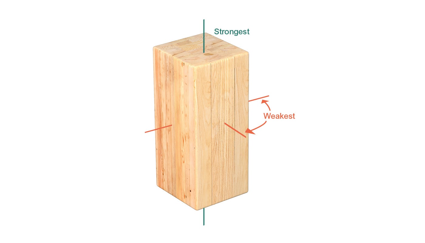
Understanding the geometry requirements presented in our literature hinges on an adequate knowledge of the intrinsic structure of wood. As a natural material, wood grows through the continuous addition of concentric layers, or rings, to its cross-section. Such growth mechanism imparts wood with its distinctive structure and anisotropic physical properties. These unique characteristics underscore the importance of considering the angle at which external forces are applied in relation to the grain direction.
While wood exhibits remarkable resistance to forces applied along the grain, the weaker bonds between its linear fibers mean that wood material can be split relatively easily by forces applied perpendicular to the grain. Because wood is more prone to splitting along the grain, the geometry requirements corresponding to this direction (end distance and spacing of fasteners in a row) are generally larger than those needed for spacings and distances across the grain (edge distance and spacing between rows of fasteners). This anisotropic physical property of wood is also the reason behind the impact of load direction on spacing requirements.
STSs and the Wedge Effect
The specific design features of the selected fasteners play a pivotal role in determining the pertinent geometry requirements. STSs are equipped with a self-tapping tip that facilitates fast and easy installation. While this confers a notable advantage in terms of preparation and installation efficiency, a phenomenon known as the wedge effect can be introduced if connections are not properly detailed.
During the installation of a STS, wood material is not removed but is rather compressed and densified around the threads. This localized densification of the wood fibers, referred to as the wedge effect, can introduce additional stresses during installation that may contribute to splitting. These additional stresses are factored into the geometry requirements provided in our design guides.
MTC Solutions offers two types of screws with distinct thread designs. Designers familiar with these screws will notice that the requirements for partially threaded screws are larger than those for fully threaded screws. This discrepancy arises from the tip design of the screws and its consequential influence on the wedge effect.
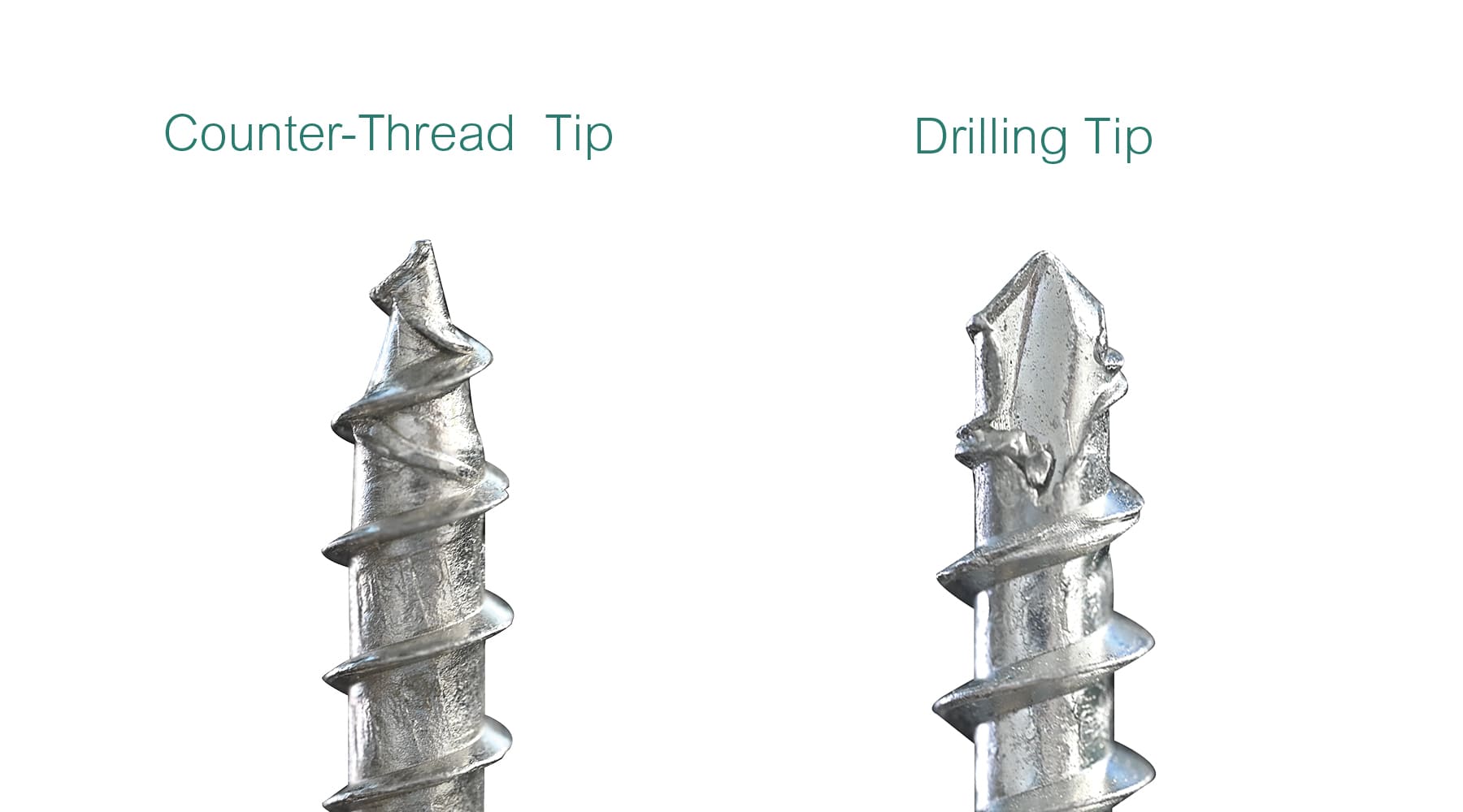
A partially threaded screw features a counter-thread tip designed to securely grip the wood and quickly engage with its fibers. Conversely, a fully threaded screw boasts a specialized drilling tip that functions akin to a drill bit. Even though no material is removed during the installation of a fully threaded screw, the drilling tip design diminishes the overall impact of the wedge effect, resulting in smaller spacing requirements.
Further reductions in spacing requirements may necessitate the consideration of predrilling. This process involves removing material in advance to alleviate local stresses around the screw threads. For more information about the differences between fasteners offered by MTC Solutions, please consult the technical blog post titled “Partially Threaded Versus Fully Threaded Screws.”
Choosing the Appropriate Geometry Requirements
Navigating the varying geometry requirements stipulated in different resources poses a significant challenge for designers. For instance, the National Design Specification for Wood Construction (NDS) mandates a minimum end distance of 7D for dowel-type fasteners in softwood connections under parallel-to-grain tension. (Note that the NDS values are generic and based on dowel-type fasteners with either large or small diameters.) In contrast, the Evaluation Service Report (ESR)-3179 from the ICC Evaluation Service and the MTC Solutions Structural Screw Catalog prescribe 15D and 6D respectively for the same scenario.
This disparity can be primarily ascribed to the different wood products or specific areas of wood members from which these values are derived. To assist designers in negotiating these geometry requirements, MTC Solutions recommends the following approach. When dealing with connections involving glued-laminated timber (glulam), the requirements outlined in the ESRs should take precedence. For connections based on cross-laminated timber (CLT), the choice hinges on the location of fastener application. For narrow-edge applications, the specific requirements in the NDS merit priority; for panel-face applications, the values in the MTC Solutions Structural Screw Catalog should be followed. Figure 4 provides a visual representation of this selection method.
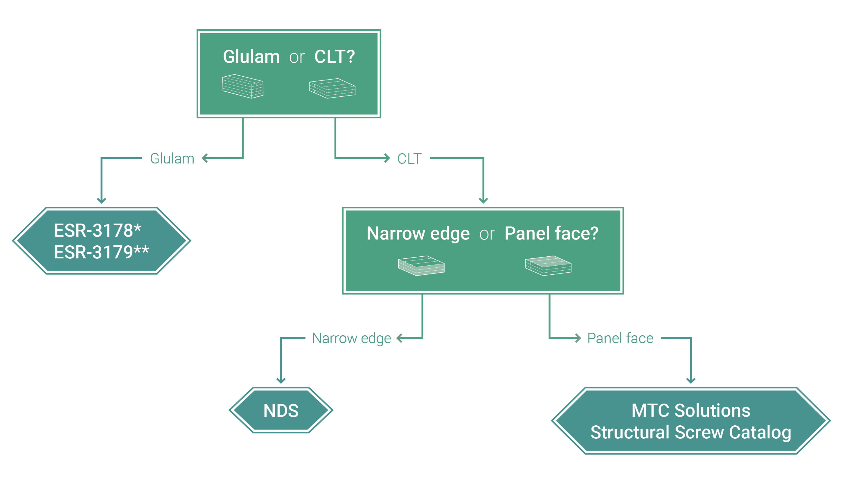
(* for fully threaded screws; ** for partially threaded screws)
Part 1 of this technical blog series offers insights into spacing values and illuminates the differences between fully and partially threaded fasteners. Part 2 covers the geometry requirements specific to CLT and Douglas-fir connections, while also addressing special considerations for connections employing axially loaded inclined STSs.
For comprehensive design guidance, the MTC Solutions Structural Screw Catalog provides detailed instructions and considerations for establishing connections with STSs. Should you require further information or assistance, please contact our Technical Support Team. 🙂
Register for a Technical Learning Session
Sign up for MTC Newsletter and keep up to date with all our progress.