
All buildings experience some degree of movement due to wind and seismic lateral loading. In high seismic regions, these demands can approach or even exceed the maximum drift requirements prescribed in design standards. For structural engineers, this introduces added complexity at gravity connections, where solutions must fit within tight beam geometries, provide the required structural capacity, and continue to support the load as the building moves.
This blog post will outline why drift performance at beam hanger connections matters, how we at MTC evaluated this performance, and the results of how our hangers performed in drift testing.
6-minute read.
Why Does Drift Performance Matter at a Beam Hanger Connection?
Buildings experience lateral movement under wind and seismic loading, and interstory drift is an unavoidable part of structural response. NBCC and ASCE 7 provide drift limits that must be accommodated, with a maximum tabulated value of 2.5%; however, the actual drift demand used in design may depend on several factors including:
In practice, required drift limits may vary from tabulated values, and these limits apply to overall building response rather than to individual connections.
While beam hangers are not part of the lateral force resisting system, they must remain functional under the deformation imposed by that system. If a connection cannot tolerate the required movement, damage or loss of gravity load path may occur even when the primary lateral system performs as intended.
In addition, drift does not distribute uniformly across a building. Individual beam-to-column connections may experience rotational demands that exceed the average story drift while others experience less.
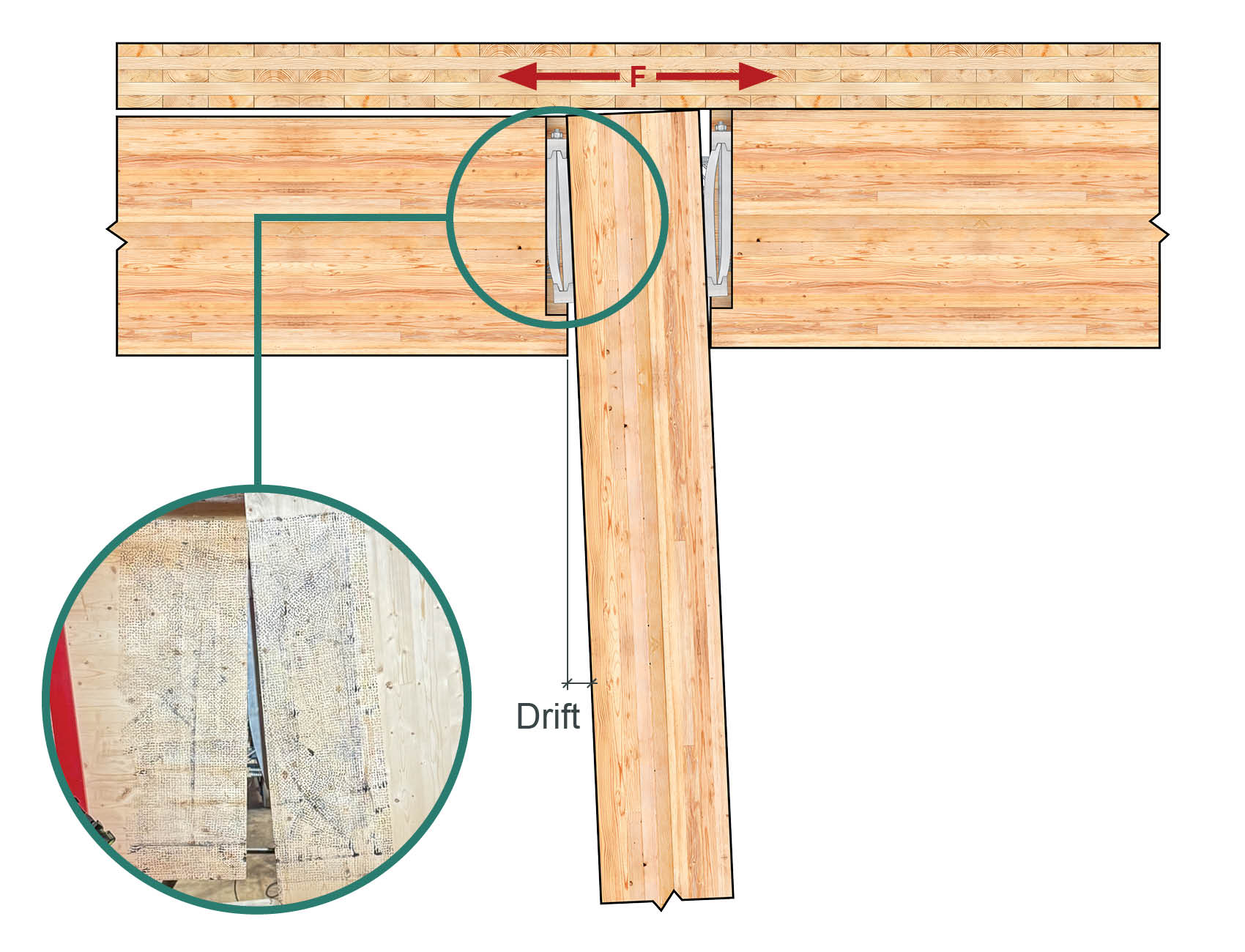
Figure 1. Interstory Drift Causing Relative Rotation Accommodated by the Beam Hanger
Drift demand at a beam hanger connection is influenced by several factors, including beam depth, the hanger’s vertical placement within a beam, connection geometry, and interaction with surrounding elements, such as floor systems. Some of these factors can be estimated analytically, while others are best captured through testing, which MTC Solutions has undertaken in two test programs.
You might be asking, “how were these tests conducted?” or “how did MTC hangers perform?”. Let’s find out!
How is a Beam Hanger System Tested to Evaluate its Drift Performance?
Drift performance can be evaluated using several testing approaches, all of which aim to induce rotation at a connection and measure its ability to accommodate deformation while supporting load. Cyclic testing is generally preferred, as it reflects the reversing nature of seismic loading. The Consortium of Universities for Research in Earthquake Engineering (CUREE) protocol was developed specifically to simulate seismic demand in a pseudo-static cyclic loading.
In 2025, MTC Solutions completed drift testing using two complementary approaches with the CUREE protocol on APEX, MEGANT, and RICON S VS. Component-level testing allows efficient and repeatable evaluation of individual connections under controlled conditions. System-level testing, while significantly more complex and resource-intensive, captures interaction between multiple connections and provides insight into how a structure behaves as a whole.
In all tests, hangers were approximately centered vertically to reflect common detailing practice and fire cover, representing a conservative configuration with respect to rotational demand. Future testing will explore how hanger placement may affect drift performance.
First, in the component-level testing conducted at Queen’s University, a single beam-to-column connection was subjected to reversed cyclic rotation while gravity load was maintained on the beam. This approach allowed multiple connector sizes and configurations to be tested efficiently, while observing deformation mechanisms, rotation capacity, and gravity load retention.
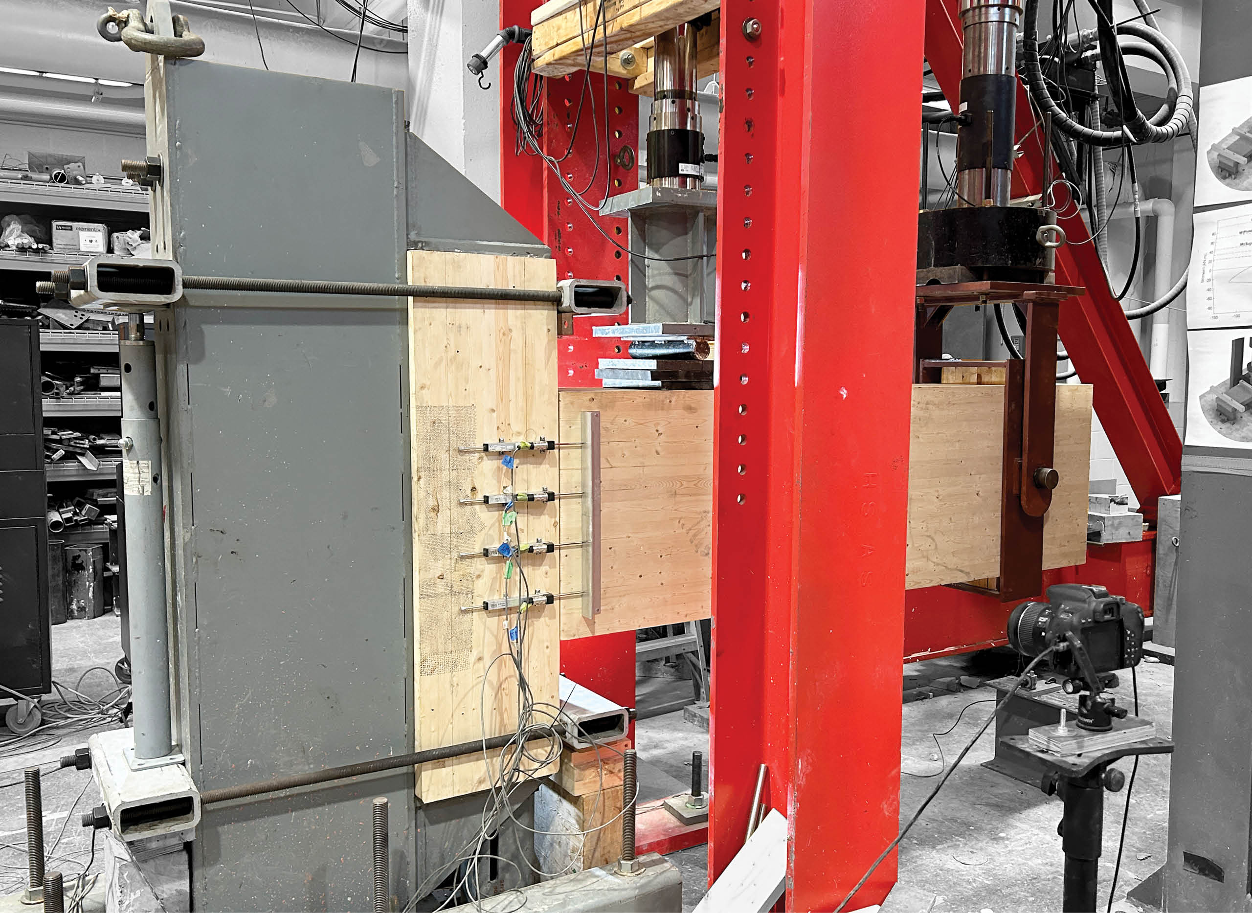
Figure 2. Component Drift Testing at Queen’s University
Then, to validate whether component-level results were representative of real building behavior, full-frame system testing was conducted at the University of Northern British Columbia (UNBC). A multi-connection beam-and-column frame was subjected to cyclic lateral displacement while supporting gravity load through floor panels. This approach allowed connection behavior to be observed in a realistic frame and was used to validate component-level testing results.
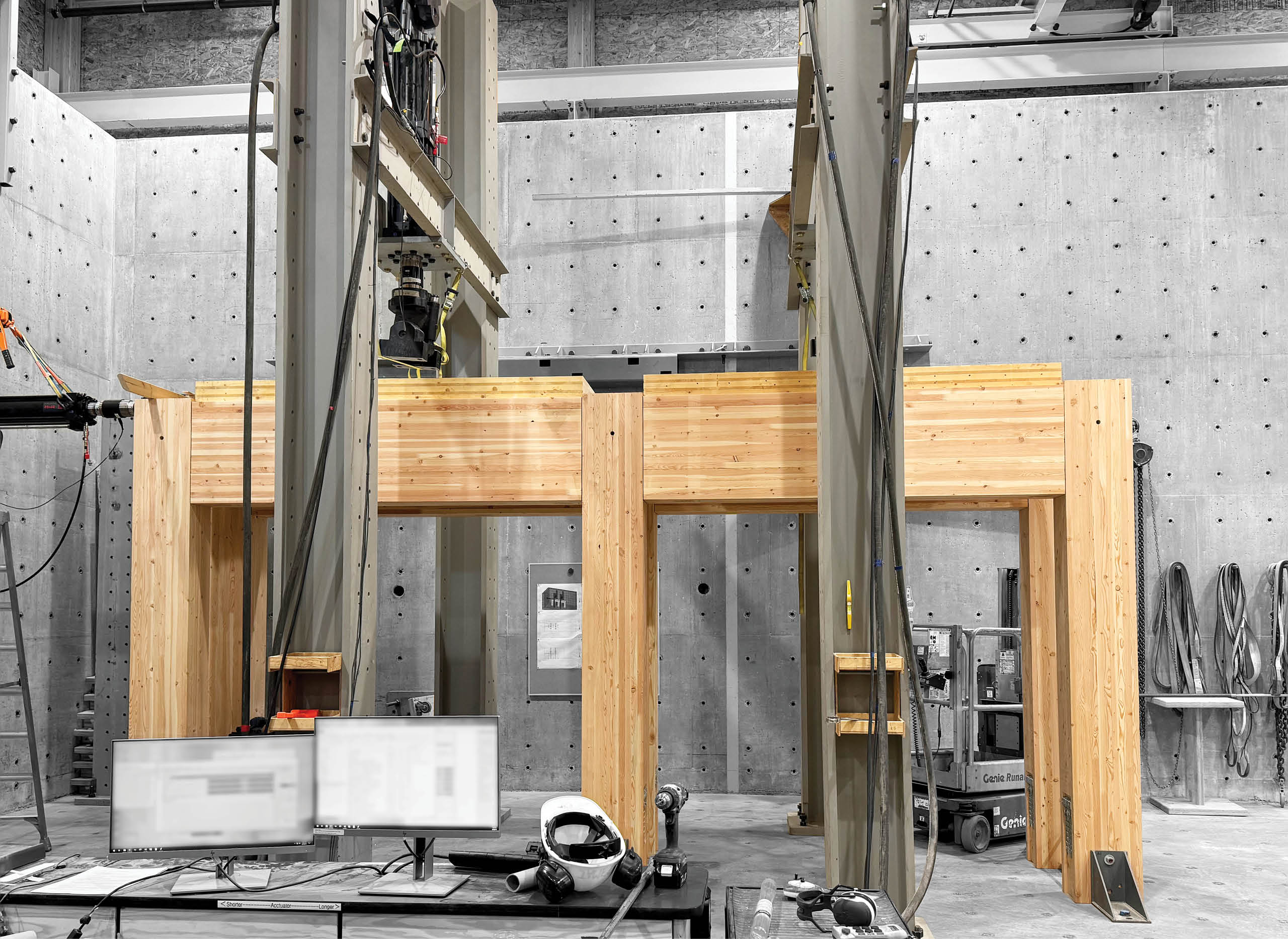
Figure 3. System Drift Testing at UNBC
How Do MTC Solutions Beam Hangers Perform Under Seismic Drift Testing?
In both test programs, MTC beam hangers accommodated drift demands far exceeding prescribed code limits without loss of load-carrying capacity.
Component-level testing showed consistent performance across all hanger types tested with no loss of gravity load. The relative rotation measured exceeded:
Testing was terminated upon reaching the rotational limits of the test setup rather than connection failure.
Full-frame system testing provided insight into how global story drift translates to local connection demand. Measured story drifts of 3.6% and 3.0% translated to higher rotational demands at the connections, reaching 4.5% for double RICON S VS and 4.1% for MEGANT. These results confirmed the expectation that connection-level demand is not uniform across a structure and may exceed global drift limits depending on connection location.
Comparison of the results from each of two test programs showed consistent deformation mechanisms between component-level and full-frame system testing (see Figure 4), supporting the use of component-level testing as a reliable method for evaluating beam hanger drift performance.
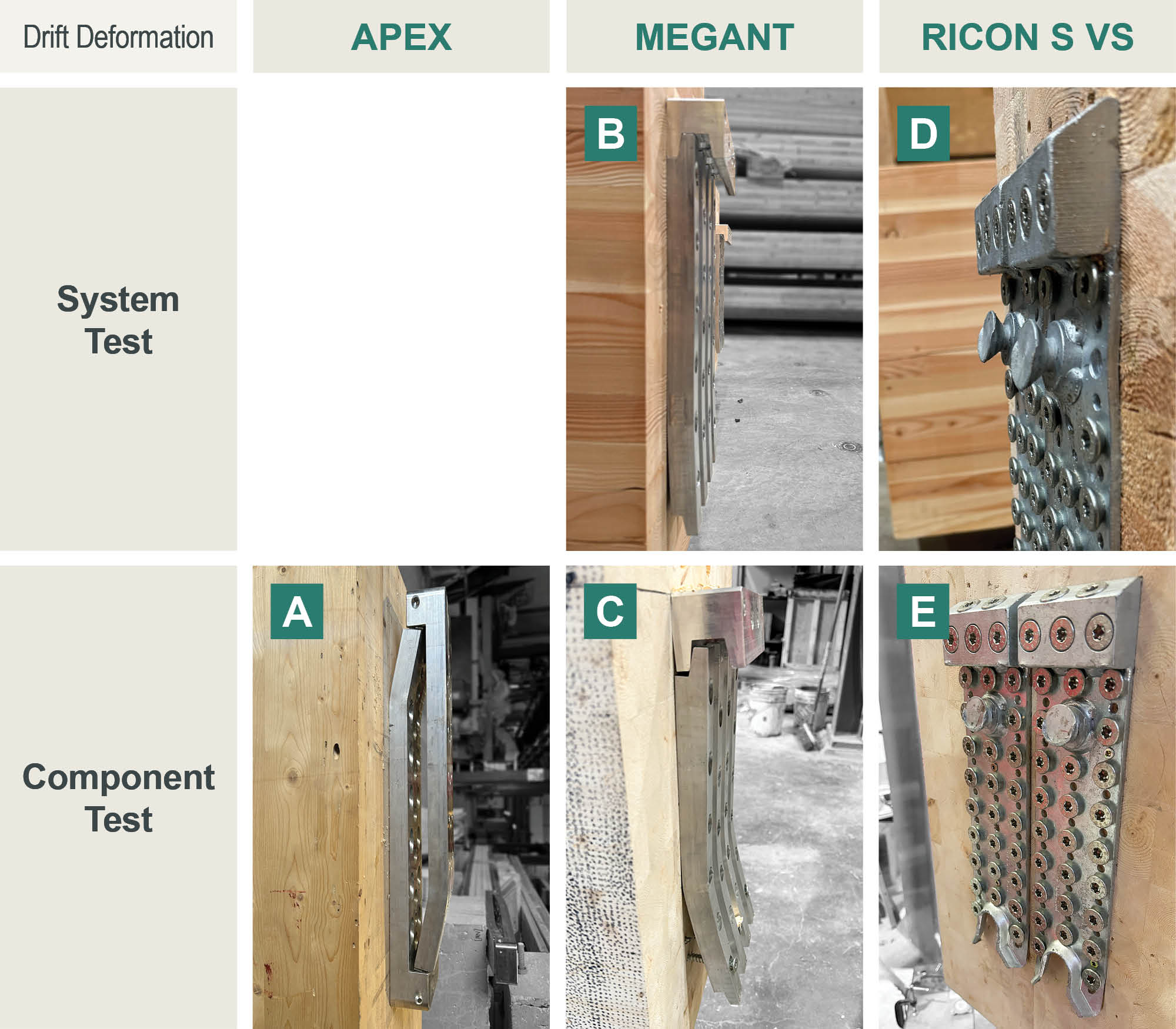
Figure 4. Drift Deformation Results Comparison: (A) Component Testing of APEX M; (B) System Testing of MEGANT 430×150; (C) Component Testing of MEGANT 430×150; (D) System Testing of Double RICON S VS XL 390×80; (E) Component Testing of Double RICON S VS XL 390×80
For Engineers of Record, these results provide confidence that MTC beam hangers can accommodate significant imposed deformation while maintaining gravity load paths.
Through ongoing research, testing, and product development, MTC Solutions focuses on advancing beam hanger systems that balance structural capacity, seismic resilience, fire performance, and constructability. These efforts are intended to support more consistent detailing, reliable installation, and predictable in-service performance across a range of mass timber applications.
If you’d like to learn more about our beam hanger systems for your North American projects, contact our Technical Support Team, and we’ll be there to guide you and your team.
Annex
Further discussion of the full-frame testing program is available in the published paper, “Impacts of Beam Hanger Rotational Stiffness on Column Resistance of Post-and-Beam Frames,” presented at the Wood Conference on Timber Engineering 2025 (Written by Walters L., Nasiri H., Tong F., Weibe L., & Tannert T.).
Register for a Technical Learning Session
Sign up for MTC Newsletter and keep up to date with all our progress.