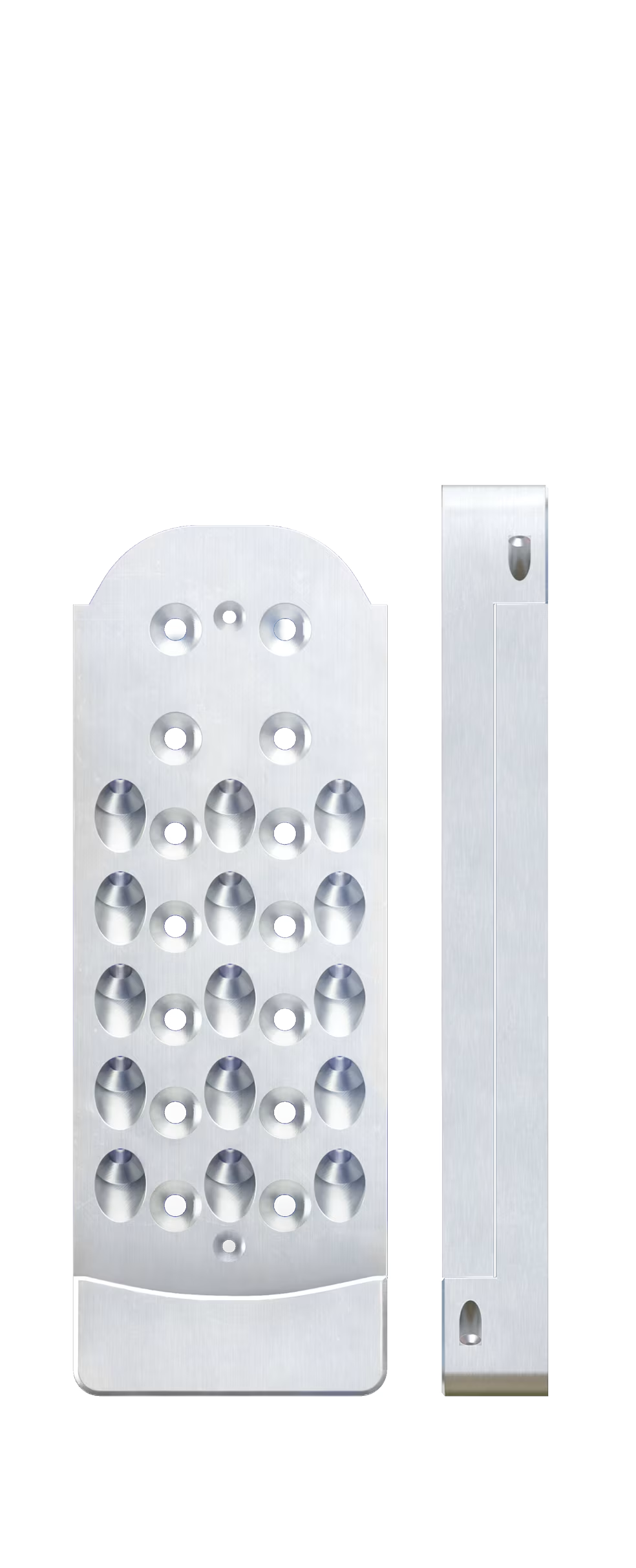
APEX
Pre-engineered Connection System

-

CA and US Engineered & Manufactured
-

ICC-ESR-5466 Certified
-

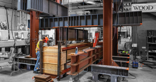
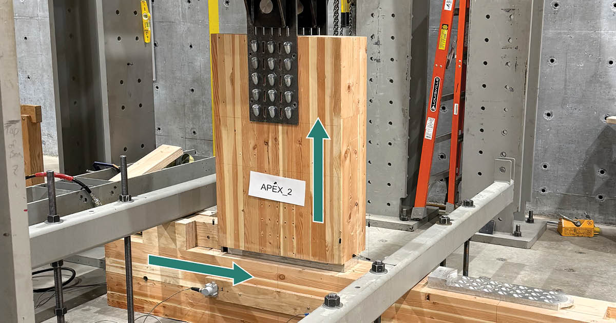
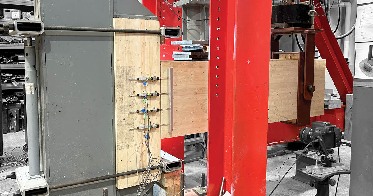
Interstory Drift Tested
-

MTC Solutions Owned
-

Download and axially tested
-

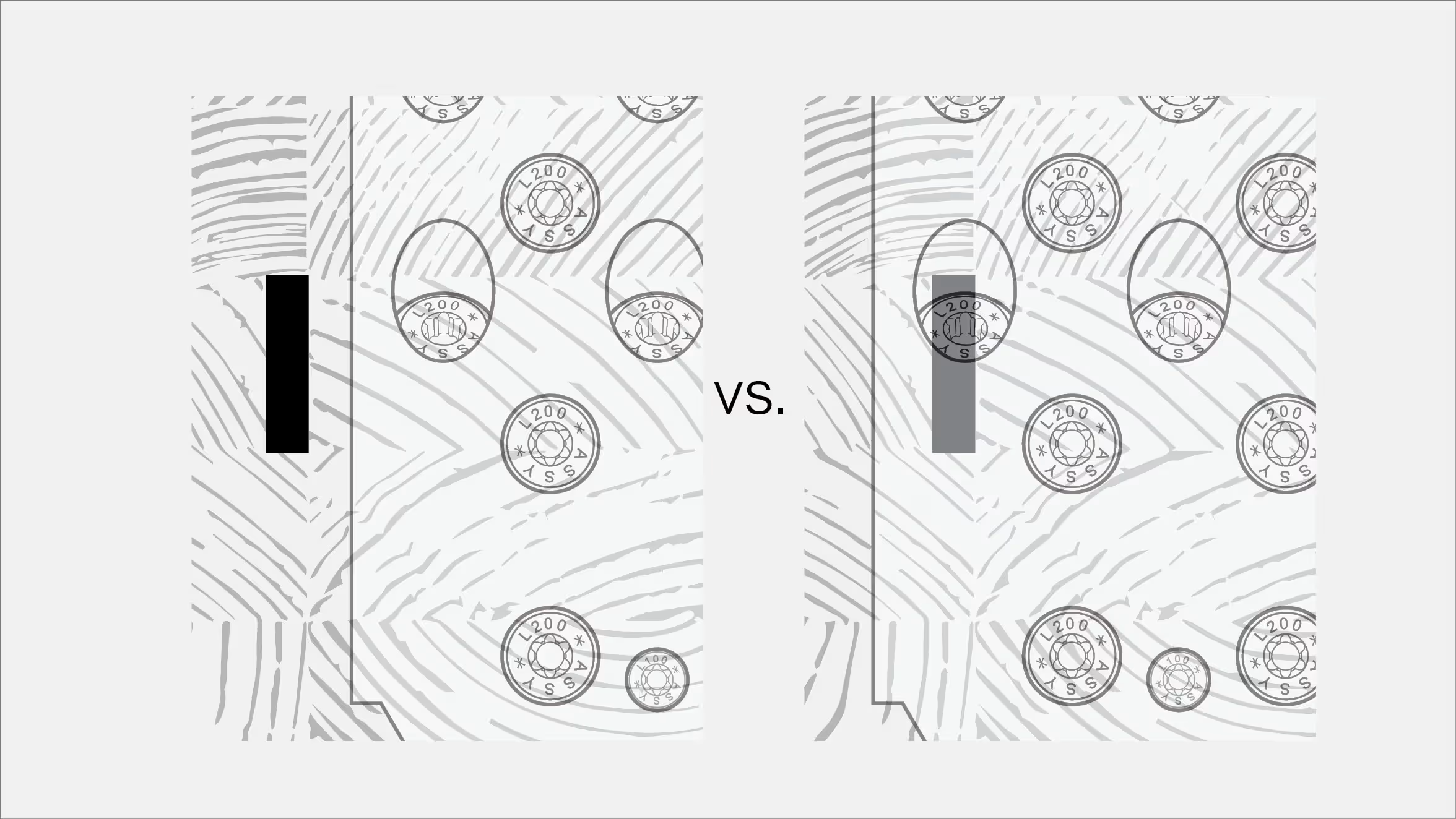
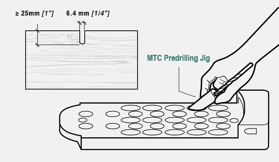
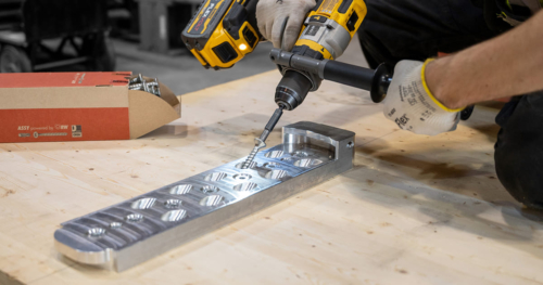
Installation Tolerances up to 1/8" (3.2mm) and 0.5°


 Uplift Capacity Range
  Axial Capacity Range
  Manufactured in
  Material
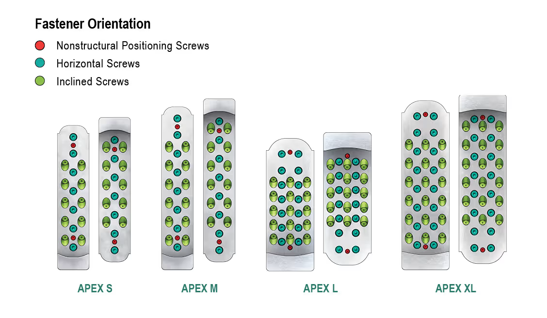
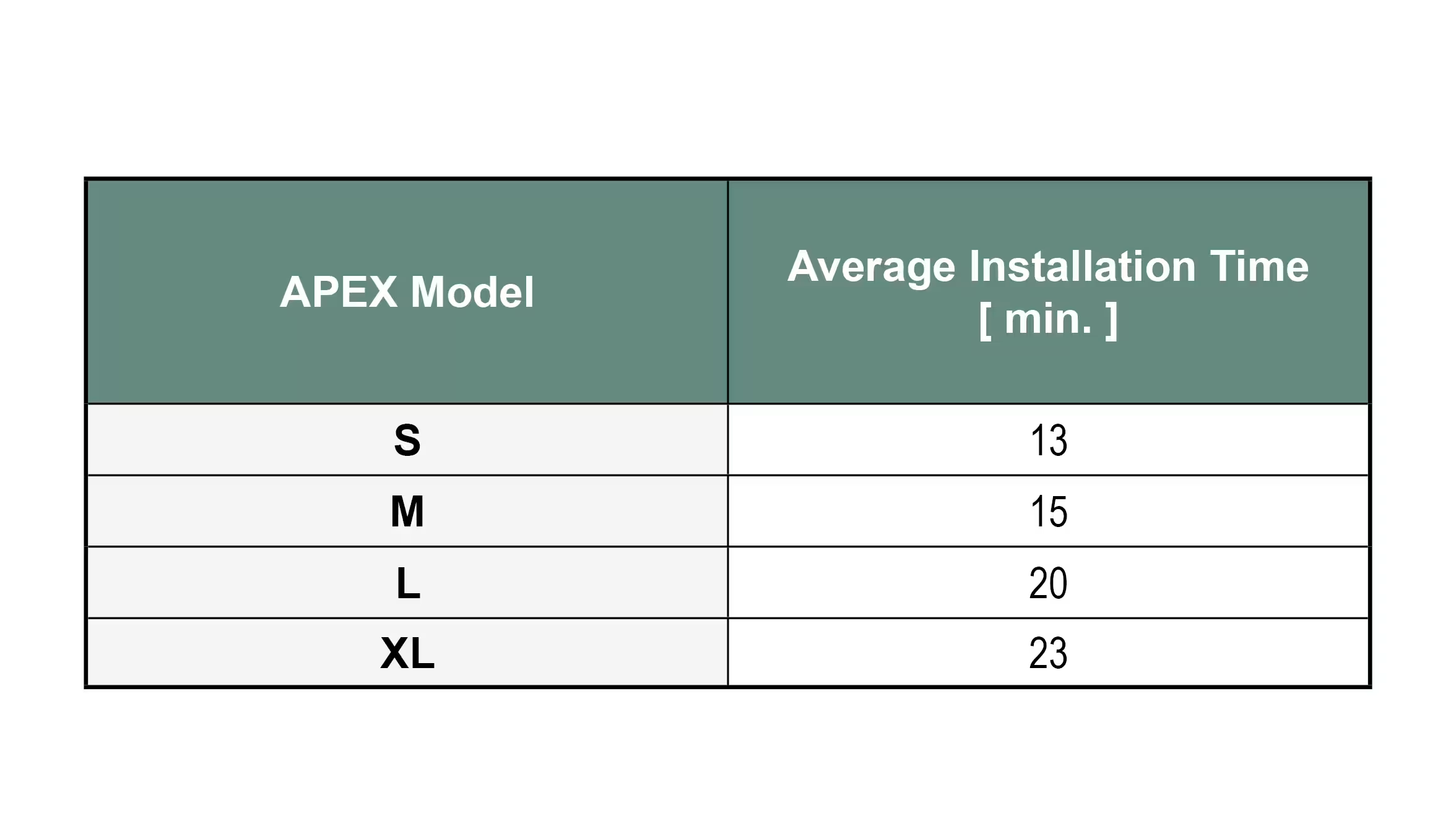
  Installation Time
 Standard & Certifications
  Seismic Compatibility
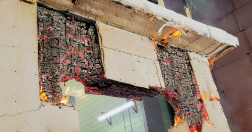
  Tested Fire Resistance Rating
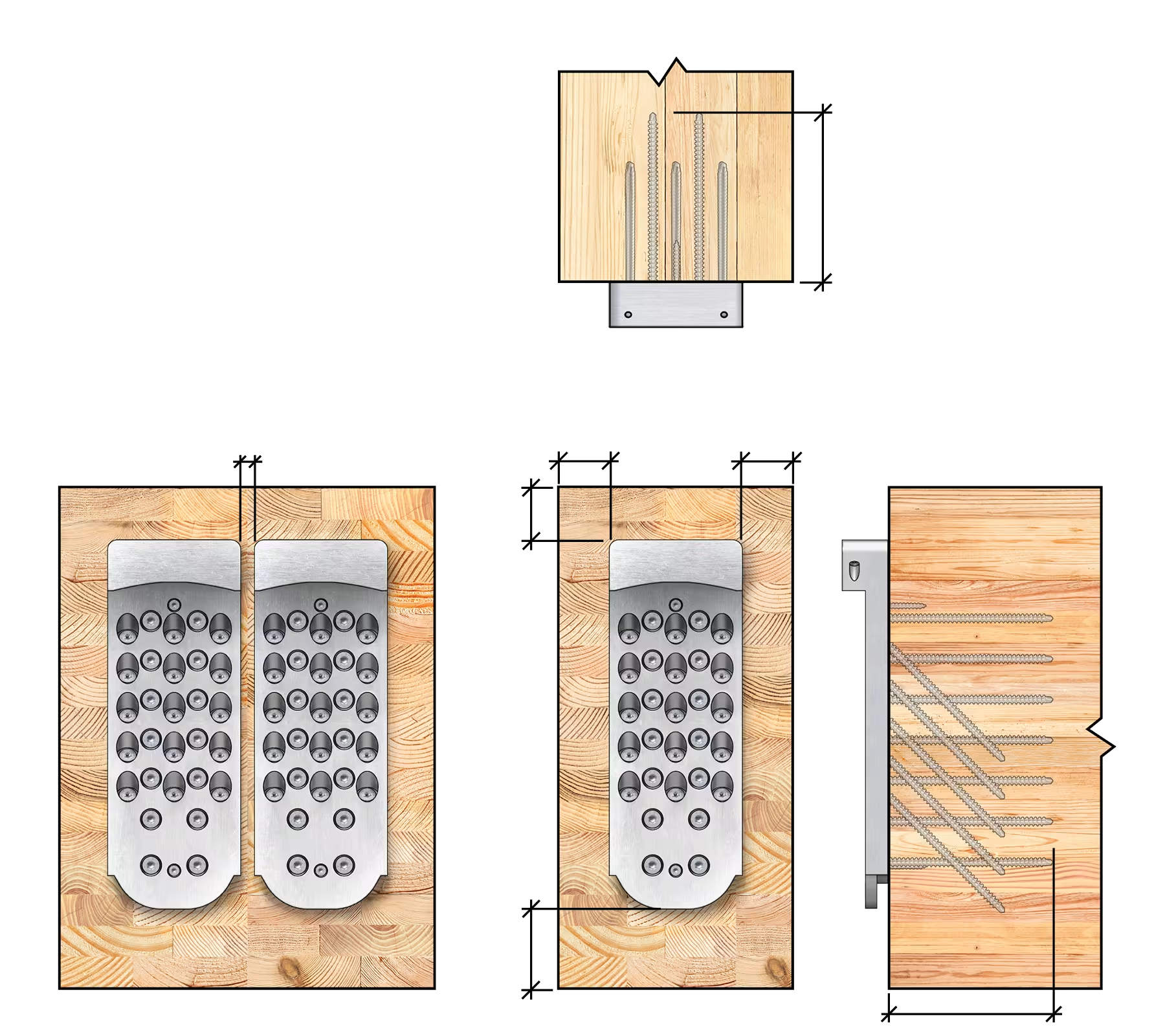
 Download Installation Guide
 MTC Tech Support

 Menu
Menu
 Beam Hanger Comparison
 Capacity
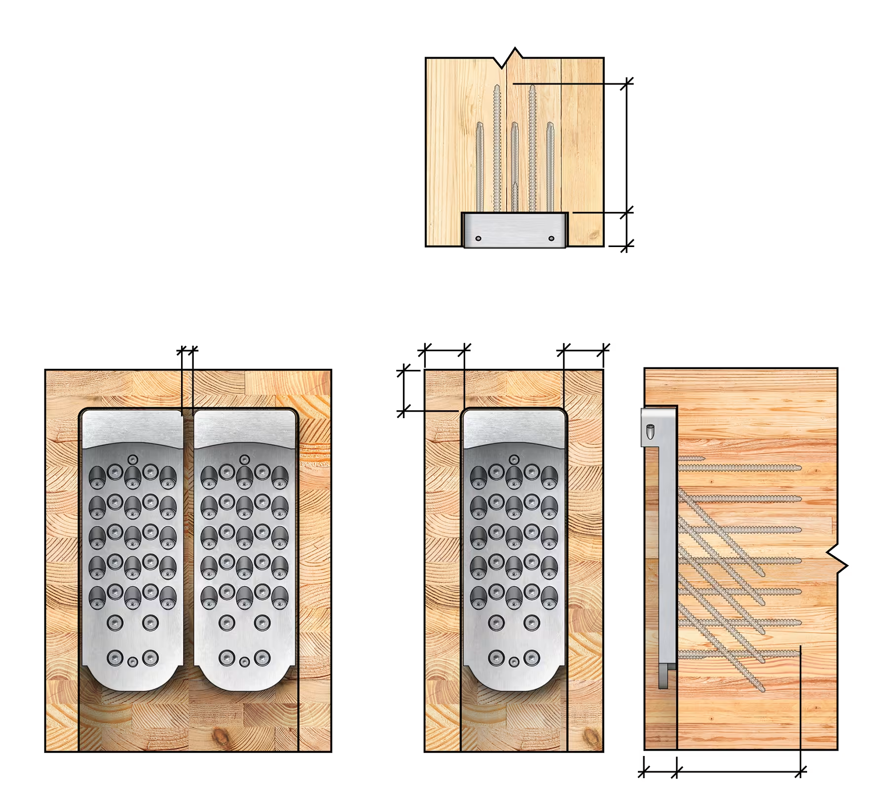
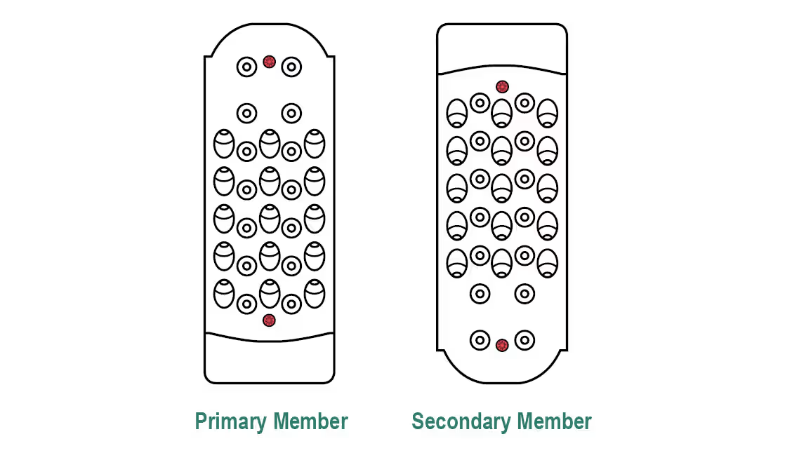
 Secondary Member Req's
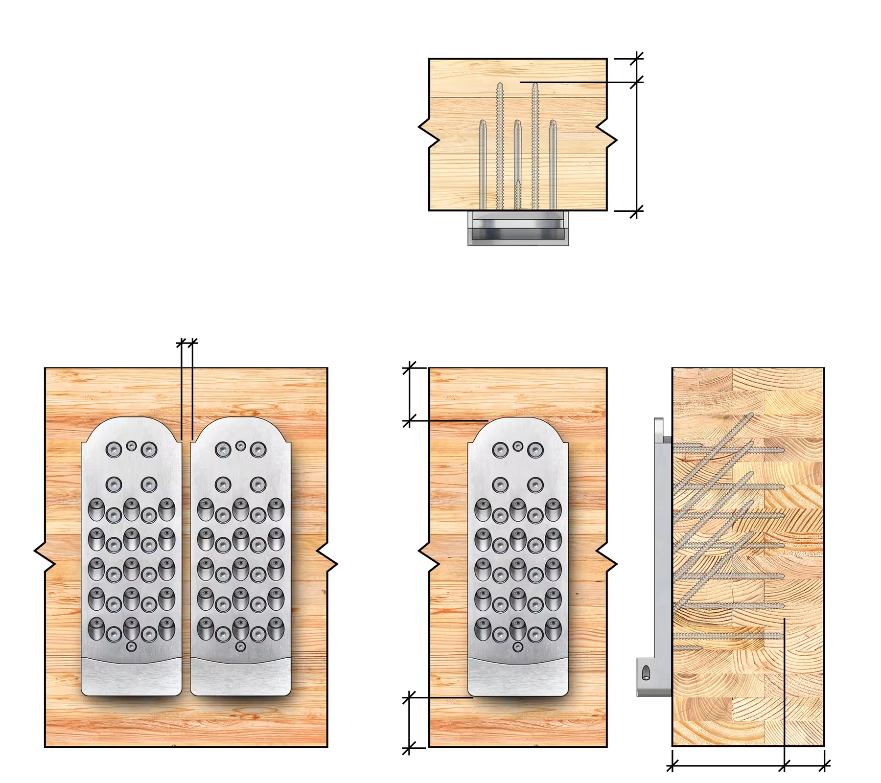
 Primary Beam Req’s
 Primary Column Req’s
 2D & 3D Geometry
 Design Guide
 Code Approval
 Installation Instructions
 Tech Blogs

