Fire resistance is a critical design requirement in mass timber construction, particularly at beam-to-column connections where concealed geometry, installation tolerances, and unbonded interfaces can create uncertainty. This uncertainty is often addressed through conservative detailing and supplemental protection, and there is growing demand for guidance that reflects real construction conditions rather than idealized assumptions.
This blog post outlines MTC APEX beam hangers’ performance under standard fire exposure, focusing on realistic beam-to-column gaps, the need for supplemental interface mitigation, and the effect of reinforcement screw heads exposure. We’ll explain how these hangers utilized a typical beam-to-column gap up to 1/8 in. [3.2 mm], with no intumescent tape or fire caulking and optimized wood cover, to achieve a 2-hr fire-resistance rating in fully loaded, full-frame test configuration!
And if you are in a hurry, here is a quick highlight of the results!
The goal was to test under realistic installation conditions rather than idealized assumptions.
6-minute read.
Why Does Fire Performance at the Beam-to-Column Gap Matter?
In practice, a small beam-to-column gap is difficult to avoid.
Construction tolerances, erection sequencing, and the geometry required to slide members into concealed connections typically result in a small unbonded interface at installation. Those gaps raise understandable concerns related to flame and heat penetration, accelerated charring, and uncertainty at concealed hardware. As a result, detailing often includes mitigation measures such as intumescent tape or fire caulking at the interface.
The question is not whether gaps exist, but how APEX performs when they do.
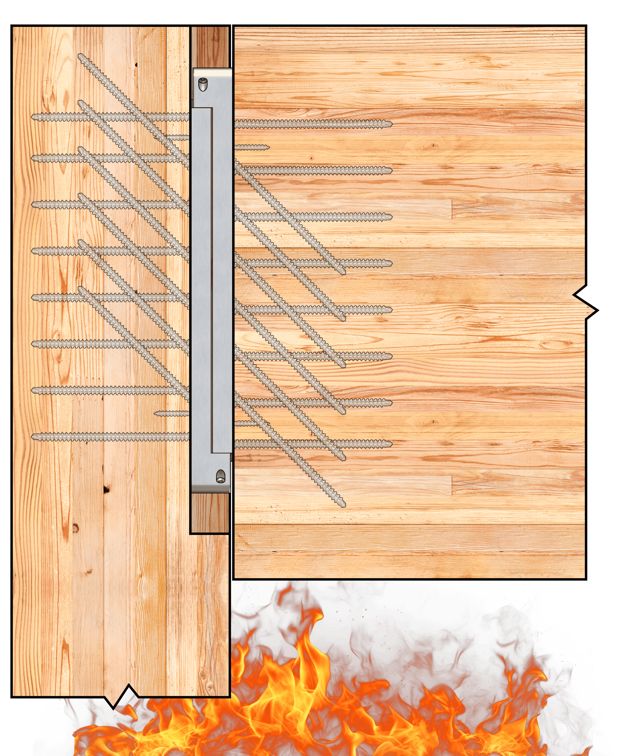
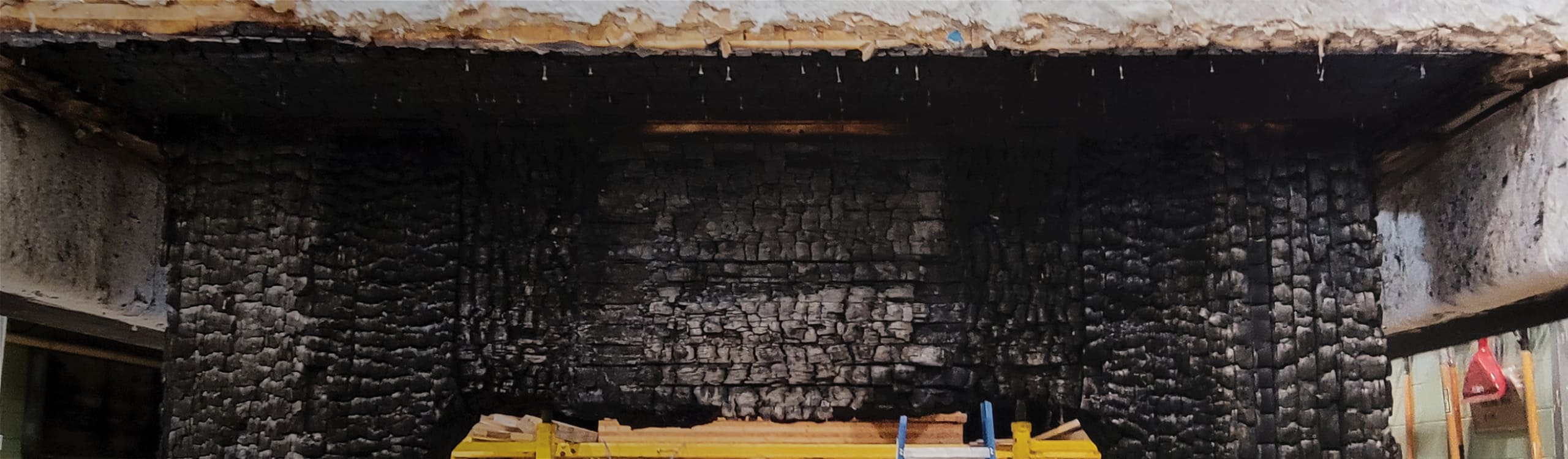
Figure 1. Unbonded APEX Beam-to-Column Connection Exposed to Fire
How was the Fire Performance of APEX Evaluated?
The phased testing approach was designed to build confidence progressively rather than relying on a single test outcome. The test program included exploration to understand key parameters followed by full-scale, fully loaded furnace testing in collaboration with FPInnovations. All tests were conducted under standard fire exposure methods as defined by CAN/ULC S101 and ASTM E119 for evaluating fire endurance of building construction assemblies in North America.
The test program evolved in three phases:
Phase 1
24 configurations were tested to identify influential parameters, including beam-to-column gap, connection detailing, and reinforcement screw exposure.
Phase 2
Based on exploration results, the next series of tests focused on the construction scenarios most representative of real project detailing, including loaded conditions.
Phase 3
A fully-loaded, full-frame, 2-hr fire test of the refined configuration was conducted with the National Research Council (NRC) and FPInnovations.
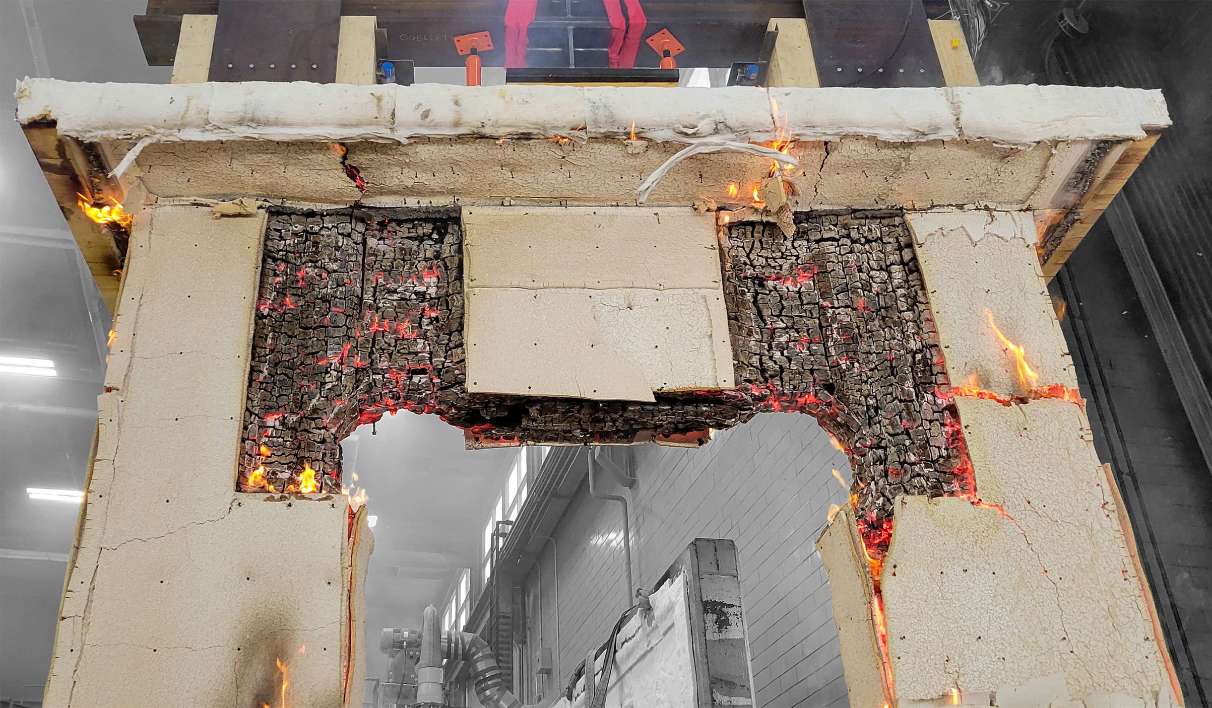
Figure 2. Full-Scale, Fully-Loaded Fire Test Conducted at NRC
The test program evaluated realistic APEX installation conditions, including reduced side and bottom wood cover relative to conservative code-based assumptions, an unbonded beam-to-column interface with a measurable gap, full-service loading during the full-scale test, and configurations with and without reinforcement screws to observe the effect of exposed screw heads.
What did the Fire Tests Show?
The final APEX configuration showed that an unbonded beam-to-column gap up to ~1/8 in. [3.2 mm], consistent with measured gaps in the full-scale test, and optimized bottom and side cover do not negatively affect fire resistance or load-carrying behavior. As a result, interface sealants such as intumescent tape or fire caulking were not required to achieve the 2-hr FRR.
Reinforcing screws that may be required for splitting resistance perpendicular to grain at APEX connections are installed with their heads exposed to the fire environment. This condition was evaluated across all six fire tests with no measurable reduction in fire resistance rating.
Practical Fire Detailing Guidance for APEX
Based on these results, to achieve an FRR up to two hours, MTC recommends the following tolerance-aware detailing guidance for APEX connectors:
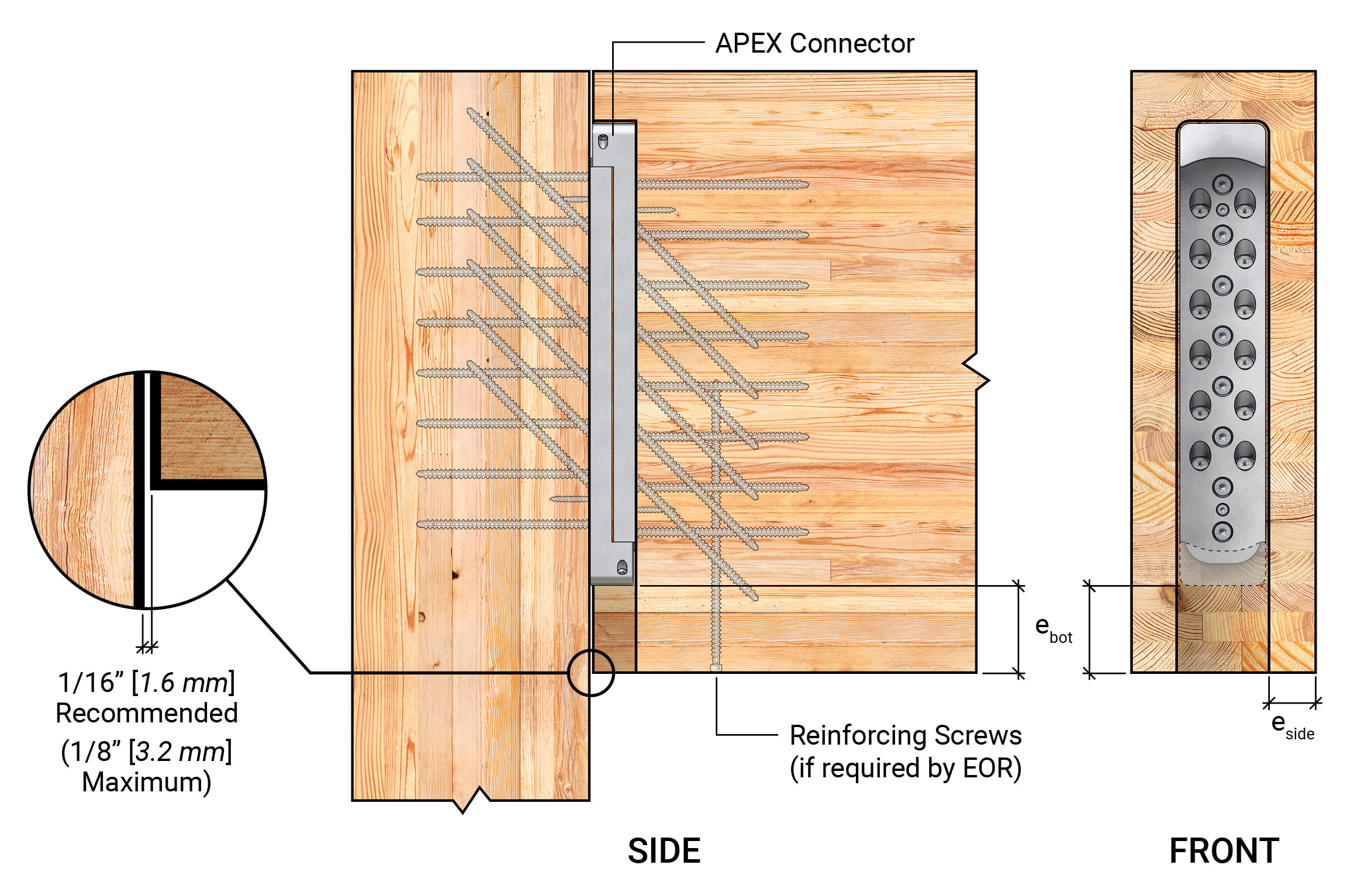
Figure 3. Recommended Fire Detailing for APEX Connectors
Fire-Tested APEX Performance Checked in Real Conditions!
A phased fire test program, culminating in a full-scale, fully loaded NRC furnace test, validated the fire performance of APEX beam hangers under realistic installation conditions. The tested configuration showed that an unbonded beam-to-column gap, realistic side and bottom wood cover, and exposed reinforcement screw heads did not prevent the connection from achieving a 2-hr fire-resistance rating.
For designers and builders, this means conservative interface treatments can be reduced where the tested APEX configuration and published geometry requirements are followed. It also means greater confidence that the connection can accommodate realistic fabrication and installation tolerances without sacrificing validated fire performance.
If you’d like to learn more about MTC’s North American-manufactured APEX beam hangers for your North American projects, download your version of the Beam Hanger Design Guide.
And as usual, if you have doubts, questions, or want to learn more, we cannot recommend enough to get in touch with the mass timber hardware specialist. Contact our Technical Support Team here, we are ready to assist.
Register for a Technical Learning Session
Sign up for MTC Newsletter and keep up to date with all our progress.