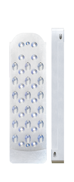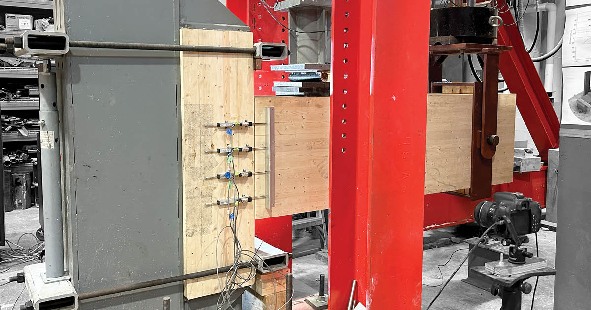
APEX MASS TIMBER HANGER

RIDGE

Pre-engineered Connection System

APEX
  • CA and US Engineered & Manufactured

  • Full-scale download tested

  • Simple, Fast, Drop-In Installation

  • MTC Solutions Owned

  • Installation Tolerances up to 1/8" (3.2mm) and 0.5°

Beam Hanger Comparison

  • RIDGE

  • RICON S VS

  • APEX

Download Capacity Range 30 - 151 kN 22 - 129 kN 159 - 316 kN
Uplift Capacity Range Design with Toe Screws 7 - 13 kN
with Clip Lock
Design with Toe Screws
Axial Capacity Range 14 - 23 kN 14 - 29 kN 13 - 32 kN
Manufactured in US & Canada Austria US & Canada
Material Aluminum Mild Steel Aluminum
Connection Type Wood-to-Wood Wood-to-Wood
Wood-to-Steel
Wood-to-Wood
Installation Time 11 to 24 mins 9 to 20 mins 11 to 23 mins
Installation Tolerances Axial 2.6 mm (3/32") 1 mm (0.039")
RICON S VS XL
3.2 mm (1/8")
Horizontal 3.2 mm (1/8") 1 mm (0.039")
RICON S VS XL
3.2 mm (1/8")
Rotational 0.5° - 0.5°
Standard & Certifications CSA O86:24
ICC-ESR-5466
CSA O86:24
ETA-15/0667 2019
CSA O86:24
ICC-ESR-5466
Seismic Compatibility Coming Soon > 4% interstory drift > 4% interstory drift
Tested Fire Resistance Rating Coming Soon N/A 2 Hour

Notes:

  1. This table is intended as a pre-selection tool only. Refer to each respective connector for full design guidelines.
  2. The EOR is responsible for verifying all aspects of the connection design.
Download Capacity Range 4.3 - 22.4 kips 2.7 - 15.0 kips 19.3 - 39 kips
Uplift Capacity Range Design with Toe Screws 1.7 - 2.3 kips
with Clip Lock
Design with Toe Screws
Axial Capacity Range 1.9 - 3.2 kips Reach out to Tech Team 2.8 - 7.1 kips
Manufactured in US & Canada Austria US & Canada
Material Aluminum Mild Steel Aluminum
Connection Type Wood-to-Wood Wood-to-Wood
Wood-to-Steel
Wood-to-Wood
Installation Time 11 to 24 mins 9 to 20 mins 11 to 23 mins
Installation Tolerances Axial 3/32" (2.6 mm) 0.039" (1 mm)
RICON S VS XL
1/8" (3.2 mm)
Horizontal 1/8" (3.2 mm) 0.039" (1 mm)
RICON S VS XL
1/8" (3.2 mm)
Rotational 0.5° - 0.5°
Standard & Certifications CSA O86:24
ICC-ESR-5466
CSA O86:24
ICC-ESR-4300
ETA-10/0189 2019
CSA O86:24
ICC-ESR-5466
Seismic Compatibility Coming Soon > 4% interstory drift > 4% interstory drift
Tested Fire Resistance Rating Coming Soon 1 Hour 2 Hour
Wood-to-Wood Design Values

Wood-to-Wood Design Values

MTC Tech Support DL Design Guide

Pre-engineered download and axial capacities of the ICC-ES certified RIDGE beam hangers in wood-to-wood configurations (derived in accordance with CSA O86:24, ASTM D7147-21*, and ICC-ESR*) along with minimum beam and column sections for 45- to 120-minute fire-resistance ratings (FRR).

Minimum Secondary Beam Section Dimensions [ mm ]
Model Configuration No FRR 45-min FRR 1-hr FRR 2-hr FRR Relative Density
[ G ]
Factored Resistance
[ kN ] Download
Factored Resistance
[ kN ] Axial
RIDGE
XS
Single 112 x 215 175 x 241 175 x 256 265 x 304 ≥ 0.42* 30 14
≥ 0.44 32 15
≥ 0.47** 36 17
≥ 0.49 40 18
Double 208 x 215 253 x 241 271 x 256 337 x 304 ≥ 0.42* 57 24
≥ 0.44 64 25
≥ 0.47** 73 29
≥ 0.49 79 31
RIDGE
S
Single 112 x 254 175 x 280 175 x 296 265 x 343 ≥ 0.42* 56 15
≥ 0.44 60 16
≥ 0.47** 68 18
≥ 0.49 73 20
Double 208 x 254 253 x 280 271 x 296 337 x 343 ≥ 0.42* 82 26
≥ 0.44 101 27
≥ 0.47** 135 31
≥ 0.49 121 34
RIDGE
M
Single 112 x 293 175 x 320 175 x 336 265 x 382 ≥ 0.42* 74 16
≥ 0.44 79 17
≥ 0.47** 90 19
≥ 0.49 98 21
Double 208 x 293 253 x 320 271 x 336 337 x 382 ≥ 0.42* 106 27
≥ 0.44 129 29
≥ 0.47** 172 33
≥ 0.49 154 36
RIDGE
L
Single 112 x 332 175 x 360 175 x 376 265 x 421 ≥ 0.42* 98 17
≥ 0.44 103 17
≥ 0.47** 118 20
≥ 0.49 128 22
Double 208 x 332 253 x 360 271 x 376 337 x 421 ≥ 0.42* 131 28
≥ 0.44 156 30
≥ 0.47** 208 34
≥ 0.49 186 37
RIDGE
XL
Single 112 x 401 175 x 429 175 x 445 265 x 489 ≥ 0.42* 115 18
≥ 0.44 122 19
≥ 0.47** 139 21
≥ 0.49 151 23
Double 208 x 401 253 x 429 271 x 445 337 x 489 ≥ 0.42* 171 30
≥ 0.44 202 32
≥ 0.47** 271 36
≥ 0.49 240 39

*Requires minimum specified longitudinal shear strength, fv, of 1.5 MPa.

**Requires minimum specified longitudinal shear strength, fv, of 2.5 MPa and minimum specified tension perpendicular to grain, ftp, of 0.51 MPa.

Notes:

  1. Connection design must meet all relevant requirements of the General Notes to the Designer section of the Beam Hanger Design Guide
  2. Tabulated factored resistances are applicable for wood-to-wood connections only. Screw installation must follow the patterns presented in the Installation section.
  3. The listed connector resistances may be limited by the splitting resistance perpendicular to grain and the effective shear resistance of the timber members. Refer to Beam Hanger Design Guide Appendix C for more information and available reinforcement strategies. It is the responsibility of the EOR to ensure the primary and secondary members have adequate capacity to resist connection forces.
  4. Factored resistances provided do not account for combined loading in multiple directions. Combined gravity and axial loading must be verified per Beam Hanger Design Guide eq. 1 (Page 13).
  5. Tabulated factored resistances assume adequate load transfer at the beam end. Where gaps or voids are present, engineering verification may be required.
  6. Tabulated factored resistances apply to both Package A and Package B. Package A is permitted only where primary member fasteners are installed into side or parallel grain.
  7. Due to axial tolerance, some slip is expected before the connector develops the tabulated axial factored resistances shown.
  8. Tabulated factored resistances for double hanger configurations assume equal load distribution between hangers.

Minimum Secondary Beam Section Dimensions [ in. ]
Model Configuration No FRR 1-hr FRR 2-hr FRR Specific Gravity [ G ] Allowable Loads
[ lb. ] Download
Allowable Loads
[ lb. ] Axial
RIDGE
XS
Single 4-7/16 x 8-17/32 6-29/32 x 10-1/8 9-1/2 x 12-1/32 ≥ 0.42 4,300 1,930
≥ 0.46* 4,650 2,110
≥ 0.50 5,100 2,300
≥ 0.55 5,100 2,540
Double 8-7/32 x 8-17/32 10-11/16 x 10-1/8 13-9/32 x 12-1/32 ≥ 0.42 8,600 3,280
≥ 0.46* 9,350 3,600
≥ 0.50 10,250 3,920
≥ 0.55 10,250 4,310
RIDGE
S
Single 4-7/16 x 10-1/16 6-29/32 x 11-21/32 9-1/2 x 13-9/16 ≥ 0.42 7,500 2,080
≥ 0.46* 8,200 2,290
≥ 0.50 9,000 2,490
≥ 0.55 9,000 2,740
Double 8-7/32 x 10-1/16 10-11/16 x 11-21/32 13-9/32 x 13-9/16 ≥ 0.42 12,600 3,550
≥ 0.46* 16,400 3,890
≥ 0.50 15,450 4,240
≥ 0.55 17,450 4,670
RIDGE
M
Single 4-7/16 x 11-19/32 6-29/32 x 13-7/32 9-1/2 x 15-3/32 ≥ 0.42 10,700 2,190
≥ 0.46* 11,700 2,400
≥ 0.50 12,850 2,610
≥ 0.55 12,850 2,880
Double 8-7/32 x 11-19/32 10-11/16 x 13-7/32 13-9/32 x 15-3/32 ≥ 0.42 16,050 3,720
≥ 0.46* 21,650 4,080
≥ 0.50 19,700 4,440
≥ 0.55 22,250 4,900
RIDGE
L
Single 4-7/16 x 13-1/8 6-29/32 x 14-3/4 9-1/2 x 16-5/8 ≥ 0.42 13,950 2,260
≥ 0.46* 15,200 2,480
≥ 0.50 16,750 2,700
≥ 0.55 16,750 2,970
Double 8-7/32 x 13-1/8 10-11/16 x 14-3/4 13-9/32 x 16-5/8 ≥ 0.42 19,550 3,840
≥ 0.46* 26,250 4,210
≥ 0.50 23,950 4,590
≥ 0.55 27,000 5,060
RIDGE
XL
Single 4-7/16 x 15-13/16 6-29/32 x 17-3/8 9-1/2 x 19-9/32 ≥ 0.42 18,550 2,410
≥ 0.46* 20,250 2,650
≥ 0.50 22,400 2,880
≥ 0.55 22,400 3,180
Double 8-7/32 x 15-13/16 10-11/16 x 17-3/8 13-9/32 x 19-9/32 ≥ 0.42 26,850 4,110
≥ 0.46* 36,150 4,510
≥ 0.50 32,900 4,910
≥ 0.55 37,100 5,400

*Requires minimum design shear strength, fv, of 300 psi.

Notes:

  1. Connection design must meet all relevant requirements of the General Notes to the Designer section of the Beam Hanger Design Guide
  2. Tabulated allowable loads are applicable for wood-to-wood connections only. Screw installation must follow the patterns presented in the Installation section.
  3. The listed connector resistances may be limited by the splitting resistance perpendicular to grain and the effective shear resistance of the timber members. Refer to Beam Hanger Design Guide Appendix C for more information and available reinforcement strategies. It is the responsibility of the EOR to ensure the primary and secondary members have adequate capacity to resist connection forces.
  4. Allowable loads provided do not account for combined loading in multiple directions. Combined gravity and axial loading must be verified per Beam Hanger Design Guide eq. 1 (Page 14).
  5. Tabulated allowable loads assume adequate load transfer at the beam end. Where gaps or voids are present, engineering verification may be required.
  6. Tabulated allowable loads apply to both Package A and Package B. Package A is permitted only where primary member fasteners are installed into side or parallel grain.
  7. Due to axial tolerance, some slip is expected before the connector develops the tabulated axial allowable loads shown.
  8. Tabulated allowable loads for double hanger configurations assume equal load distribution between hangers.
Secondary Member Requirements

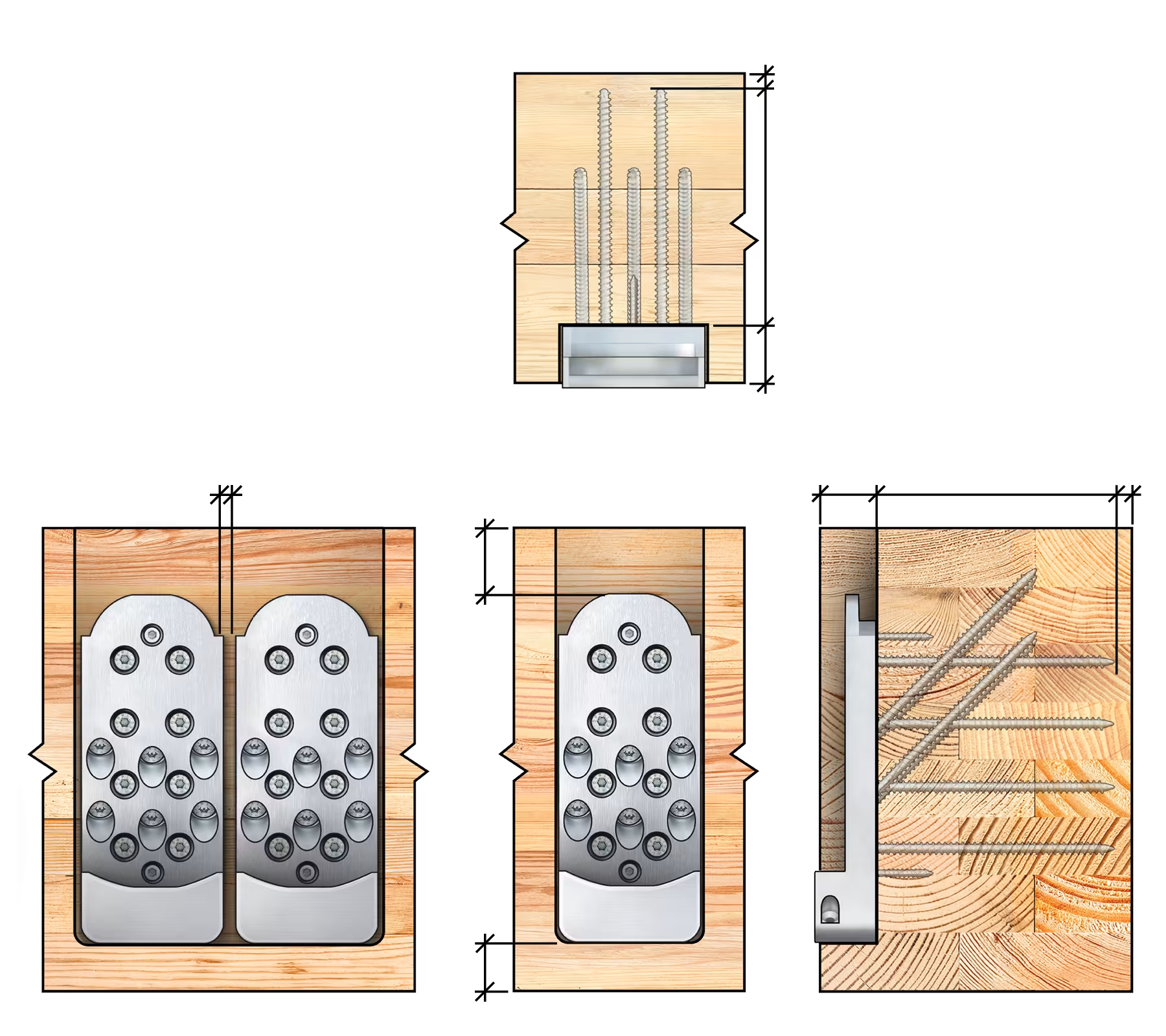
Secondary Member Geometry Requirements

Unhoused

  • Ip
  • Sd
  • eside
  • eside
  • etop
  • ebot
  • Ip

Housed

  • Ip
  • dh
  • dh
  • Sd
  • eside
  • eside
  • etop
  • ebot
  • Ip

Geometry Requirements [ mm ]
Model lp etop No FRR 45-min FRR 1-hr FRR 2-hr FRR dh sd
eside ebot eside ebot eside ebot eside ebot
RIDGE XS 150 10 12 29 44 54 44 70 89 117 38 8
RIDGE S 150 10 12 29 44 54 44 70 89 117 38 8
RIDGE M 150 10 12 29 44 54 44 70 89 117 38 8
RIDGE L 150 10 12 29 44 54 44 70 89 117 38 8
RIDGE XL 150 10 12 29 44 54 44 70 89 117 38 8

Notes:

  1. Connection design must meet all relevant requirements of the General Notes to Designer and General Notes to Installer sections, as well as all minimum geometry requirements. Download a copy of the Beam Hanger Design Guide
  2. Tabulated values presented are the minimum required unless noted otherwise. Tabulated values for lp are to the deepest screw penetration and are fixed. Tabulated values for dh are maximum values based on a gap between primary and secondary member of 1.6 mm [ 1/16 in. ]. Larger gaps will reduce dh accordingly.
  3. For single-connector configurations with an FRR, the tabulated side and bottom cover dimensions are based on standard CSA O122:25 beam widths. Due to the corner rounding effect (CSA O86:24 Clause B.4.5), these dimensions are interdependent; alternate width and depth combinations may be used provided the required pre-protection cover around the connector is maintained.


Geometry Requirements [ in. ]
Model lp etop No FRR 1-hr FRR 2-hr FRR dh sd
eside ebot eside ebot eside ebot
RIDGE XS 5-29/32 13/32 1/2 1-1/8 1-31/32 2-23/32 3-1/32 4-5/8 1-1/2 5/16
RIDGE S 5-29/32 13/32 1/2 1-1/8 1-31/32 2-23/32 3-1/32 4-5/8 1-1/2 5/16
RIDGE M 5-29/32 13/32 1/2 1-1/8 1-31/32 2-23/32 3-1/32 4-5/8 1-1/2 5/16
RIDGE L 5-29/32 13/32 1/2 1-1/8 1-31/32 2-23/32 3-1/32 4-5/8 1-1/2 5/16
RIDGE XL 5-29/32 13/32 1/2 1-1/8 1-31/32 2-23/32 3-1/32 4-5/8 1-1/2 5/16

Notes:

  1. Connection design must meet all relevant requirements of the General Notes to Designer and General Notes to Installer sections, as well as all minimum geometry requirements. Download a copy of the Beam Hanger Design Guide.
  2. Tabulated values presented are the minimum required unless noted otherwise. Tabulated values for lp are to the deepest screw penetration and are fixed. Tabulated values for dh are maximum values based on a gap between primary and secondary member of 1.6 mm [ 1/16 in. ]. Larger gaps will reduce dh accordingly.
  3. For single-connector configurations with an FRR, the tabulated side and bottom cover dimensions are based on standard ANSI A190.1 beam widths. Due to the corner rounding effect, these dimensions are interdependent; alternate width and depth combinations may be used provided the required fire-protection cover around the connector is maintained.
Primary Column Requirement

Primary Member Geometry Requirements - Beam/Girder

Unhoused

  • eback
  • Ip, A or B
  • Sd
  • etop
  • ebot
  • Ip, A or B
  • eback

Primary Member Geometry Requirements - Beam/Girder

Housed

  • eback
  • Ip, A or B
  • dh
  • Sd
  • etop
  • ebot
  • dh
  • Ip, A or B
  • eback

Primary Member Geometry Requirements - Beam/Girder

Geometry Requirements [ mm ]
Model lp* etop No FRR 45-min FRR 1-hr FRR 2-hr FRR dh sd
A B ebot eback ebot eback ebot eback ebot eback
RIDGE XS 110 150 29 10 10 35 35 51 44 98 77 38 8
RIDGE S 110 150 29 10 10 35 35 51 44 98 77 38 8
RIDGE M 110 150 29 10 10 35 35 51 44 98 77 38 8
RIDGE L 110 150 29 10 10 35 35 51 44 98 77 38 8
RIDGE XL 110 150 29 10 10 35 35 51 44 98 77 38 8

*Refer to Beam Hanger Design Guide Table 2.1( Page 20) for hardware package options.

Notes:

  1. Connection design must meet all relevant requirements of the General Notes to Designer and General Notes to Installer sections, as well as all minimum geometry requirements. Download a copy of the Beam Hanger Design Guide
  2. Tabulated values presented are the minimum required unless noted otherwise. Tabulated values for lp are to the deepest screw penetration and are fixed. Tabulated values for dh are maximum values based on a gap between primary and secondary member of 1.6 mm [ 1/16 in. ]. Larger gaps will reduce dh accordingly.
  3. For single-connector configurations with an FRR, the tabulated side and bottom cover dimensions are based on standard CSA O122:25 beam widths. Due to the corner rounding effect (CSA O86:24 Clause B.4.5), these dimensions are interdependent; alternate width and depth combinations may be used provided the required pre-protection cover around the connector is maintained.
  4. Values for etop are minimum requirements based on minimum end and edge distance, and may need to be adjusted to align with the hanger placement in the secondary


Geometry Requirements [ in. ]
Model lp* etop No FRR 1-hr FRR 2-hr FRR dh sd
A B ebot eback ebot eback ebot eback
RIDGE XS 4-11/32 5-29/32 1-1/8 3/8 13/32 1-31/32 1-23/32 3-27/32 3-1/32 1-1/2 5/16
RIDGE S 4-11/32 5-29/32 1-1/8 3/8 13/32 1-31/32 1-23/32 3-27/32 3-1/32 1-1/2 5/16
RIDGE M 4-11/32 5-29/32 1-1/8 3/8 13/32 1-31/32 1-23/32 3-27/32 3-1/32 1-1/2 5/16
RIDGE L 4-11/32 5-29/32 1-1/8 3/8 13/32 1-31/32 1-23/32 3-27/32 3-1/32 1-1/2 5/16
RIDGE XL 4-11/32 5-29/32 1-1/8 3/8 13/32 1-31/32 1-23/32 3-27/32 3-1/32 1-1/2 5/16

*Refer to Beam Hanger Design Guide Table 2.1( Page 20) for hardware package options.

Notes:

  1. Connection design must meet all relevant requirements of the General Notes to Designer and General Notes to Installer sections, as well as all minimum geometry requirements. Download a copy of the Beam Hanger Design Guide.
  2. Tabulated values presented are the minimum required unless noted otherwise. Tabulated values for lp are to the deepest screw penetration and are fixed. Tabulated values for dh are maximum values based on a gap between primary and secondary member of 1.6 mm [ 1/16 in. ]. Larger gaps will reduce dh accordingly.
  3. For single-connector configurations with an FRR, the tabulated side and bottom cover dimensions are based on standard ANSI A190.1 beam widths. Due to the corner rounding effect, these dimensions are interdependent; alternate width and depth combinations may be used provided the required fire-protection cover around the connector is maintained.
  4. Values for etop are minimum requirements based on minimum end and edge distance, and may need to be adjusted to align with the hanger placement in the secondary member.
Primary Beam Requirement

Primary Member Geometry Requirements - Post

Unhoused

  • eback
  • Ip, A or B
  • Sd
  • eside
  • eside
  • etop
  • Ip, A or B
  • eback

Primary Member Geometry Requirements - Post

Housed

  • eback
  • Ip, A or B
  • dh
  • Sd
  • eside
  • eside
  • etop
  • dh
  • Ip, A or B
  • eback

Geometry Requirements [ mm ]
Model lp* etop No FRR 45-min FRR 1-hr FRR 2-hr FRR dh sd
A B ebot eback ebot eback ebot eback ebot eback
RIDGE XS 110 150 29 10 10 35 35 51 44 98 77 38 8
RIDGE S 110 150 29 10 10 35 35 51 44 98 77 38 8
RIDGE M 110 150 29 10 10 35 35 51 44 98 77 38 8
RIDGE L 110 150 29 10 10 35 35 51 44 98 77 38 8
RIDGE XL 110 150 29 10 10 35 35 51 44 98 77 38 8

*Refer to Beam Hanger Design Guide Table 2.1 (Page 20) for hardware package options.

Notes:

  1. Connection design must meet all relevant requirements of the General Notes to Designer and General Notes to Installer sections, as well as all minimum geometry requirements. Download a copy of the Beam Hanger Design Guide
  2. Tabulated values presented are the minimum required unless noted otherwise. Tabulated values for lp are to the deepest screw penetration and are fixed. Tabulated values for dh are maximum values based on a gap between primary and secondary member of 1.6 mm [ 1/16 in. ]. Larger gaps will reduce dh accordingly.
  3. For single-connector configurations with an FRR, the tabulated side and bottom cover dimensions are based on standard CSA O122:25 beam widths. Due to the corner rounding effect (CSA O86:24 Clause B.4.5), these dimensions are interdependent; alternate width and depth combinations may be used provided the required pre-protection cover around the connector is maintained.
  4. Values for etop are minimum requirements based on minimum end and edge distance, and may need to be adjusted to align with the hanger placement in the secondary


Geometry Requirements [ in. ]
Model lp* etop No FRR 1-hr FRR 2-hr FRR dh sd
A B eside eback eside eback eside eback
RIDGE XS 4-11/32 5-29/32 1-1/8 1/2 13/32 1-31/32 1-23/32 3-1/32 3-1/32 1-1/2 5/16
RIDGE S 4-11/32 5-29/32 1-1/8 1/2 13/32 1-31/32 1-23/32 3-1/32 3-1/32 1-1/2 5/16
RIDGE M 4-11/32 5-29/32 1-1/8 1/2 13/32 1-31/32 1-23/32 3-1/32 3-1/32 1-1/2 5/16
RIDGE L 4-11/32 5-29/32 1-1/8 1/2 13/32 1-31/32 1-23/32 3-1/32 3-1/32 1-1/2 5/16
RIDGE XL 4-11/32 5-29/32 1-1/8 1/2 13/32 1-31/32 1-23/32 3-1/32 3-1/32 1-1/2 5/16

*Refer to Beam Hanger Design Guide Table 2.1 (Page 20) for hardware package options.

Notes:

  1. Connection design must meet all relevant requirements of the General Notes to Designer and General Notes to Installer sections, as well as all minimum geometry requirements. Download a copy of the Beam Hanger Design Guide.
  2. Tabulated values presented are the minimum required unless noted otherwise. Tabulated values for lp are to the deepest screw penetration and are fixed. Tabulated values for dh are maximum values based on a gap between primary and secondary member of 1.6 mm [ 1/16 in. ]. Larger gaps will reduce dh accordingly.
  3. For single-connector configurations with an FRR, the tabulated side and bottom cover dimensions are based on standard ANSI A190.1 beam widths. Due to the corner rounding effect, these dimensions are interdependent; alternate width and depth combinations may be used provided the required fire-protection cover around the connector is maintained.
  4. Values for eside are applicable for side cover for both secondary beams and columns.
  5. Values for etop are minimum requirements based on minimum end and edge distance, and may need to be adjusted to align with the hanger placement in the secondary member.
2D & 3D Geometry

2D & 3D Geometry

APEX beam hanger’s connector geometry (height, width, thickness) and downloadable 2D and 3D geometry files (.DXF, .DWG, .IFC, .STEP) for use in drawings and BIM models.

Connector
Geometry
Model
RIDGE
XS
RIDGE
S
RIDGE
M
RIDGE
L
RIDGE
XL
[ mm ]
H1 178 217 256 295 362
H2 197 236 275 314 381
W 88 88 88 88 88
T 38 38 38 38 38
Connector
Geometry
Model
RIDGE
XS
RIDGE
S
RIDGE
M
RIDGE
L
RIDGE
XL
[ in. ]
H1 7 8 9/16 10 1/16 11 5/8 14 1/4
H2 7 3/4 9 5/16 10 13/16 12 3/8 15
W 3 7/16 3 7/16 3 7/16 3 7/16 3 7/16
T 1 9/16 1 9/16 1 9/16 1 9/16 1 9/16
Model .DXF .DWG .IFC .SAT
RIDGE XS
RIDGE S
RIDGE M
RIDGE L
RIDGE XL
ALL ABOVE

Notes:

  1. Connection design must meet all relevant requirements of the General Notes to Designer and General Notes to Installer sections, as well as all minimum geometry requirements. Download a copy of the Beam Hanger Design Guide
  2. Minor manufacturing tolerances may apply; actual product dimensions may vary slightly.
Design Guide

Design Guides

Beam Hanger Design Guide

The Beam Hanger Design Guide is a practical resource for designing mass timber beam connections. It provides off-the-shelf, pre-engineered solutions such as the APEX and RIDGE, featuring tabulated design values and complete installation instructions to support project completion.

Installation Steps

Get it right the first time with fast, field-ready instructions for clean, concealed connections. Review each step below or download the RIDGE installation guide—simplified for quick reference in a black-and-white format, ideal for clipboards and printouts.

Download Installation Guide
MTC Tech Support

Tools - Use the Correct Bit

MTC Solutions fasteners should only be driven using RW bits, or appropriately sized star bits. This ensures good centering and positioning with optimal torque transmission. For the RIDGE, use an RW 40 bit for the 8 mm [ 5/16 in. ] screws.

Tools - Use the Correct Drill

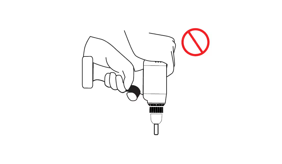
Use low-RPM, high-torque drills equipped with a feather (variable speed) trigger to install fasteners. Avoid excessive acceleration and deceleration during the drive-in process. Do not overtorque fasteners. Although impact guns are not expressly prohibited, their use is discouraged – particularly for beam hanger systems – due to an increased risk of overtorquing. Use the appropriate drill chuck size according to the fastener.

Tools - RIDGE Predrilling Jig

The RIDGE Predrilling Jig ensures precise alignment of the inclined fasteners. It guides the drill bit to create an accurate pilot hole, and ensures proper fastener seating. The hole in the jig accommodates standard imperial and metric drill bit diameters. For the 8 mm [ 5/16 in. ] inclined fasteners, pilot holes 5 mm [ 3/16 in. ] in diameter and 25 mm [ 1 in. ] long are recommended.

Fastener Layout
Fastener Layout

Each RIDGE model (XS–XL) is installed using a simplified screw pattern that includes two nonstructural positioning screws and a varying quantity of MTC-FTC structural screws (depending on the model). In the secondary member, 3/8″ × 7-7/8″ [ 10 × 200 mm ] screws are installed horizontally and inclined at a 45° angle. angle. In the primary member, horizontal screws are specified by hardware package: 5/16″ × 4-3/4″ [ 8 × 120 mm ] for Package A or 5/16″ × 6-1/4″ [ 8 × 160 mm ] for Package B.

Estimated Installation Time

This process includes the following steps:
1. Layout (~10%)
2. Positioning (~10%–15%)
3. Pilot Holes (~25%–30%)
4. Screw Installation (~45%–50%)
5. Optional Measures (not included in the time installation % breakdown)

Installation time can be reduced with efficient fabrication and site practices such as:
1.Drilling pilot holes for the nonstructural positioning screws at the time of fabrication
2.Utilizing templates to drill pilot holes for structural screws
3.Optimizing beam positioning to reduce worker fatigue

Layout - Reference Points

Begin by laying out the installation locations in the primary and secondary members using a pencil and square.

The connector’s point of reference is the top of the beam. The lower nonstructural positioning screw should be measured from that point of reference (ref).

The pocket should be at the bottom on the primary member and on the top on the secondary member.

Layout - Split Lamination Considerations

Where lamination voids are present, positioning fasteners away from the void is recommended to promote uniform load transfer. The influence of lamination voids on fasteners performance depends on their size relative to fastener geometry and their proximity to fasteners.

Positioning - Nonstructural Positioning Screw Installation

Positioning screws ensure accurate placement of the RIDGE connector. To improve accuracy and reduce time, it is recommended to predrill the nonstructural positioning screw locations during member fabrication. Install one nonstructural positioning screw into the hole highlighted at the top of the plate. Check to ensure alignment is maintained and then install the second nonstructural positioning screw into the hole highlighted at the bottom of the plate.

Pilot Holes - Recommendations

Pilot holes are optional; however, they facilitate screw thread engagement, help reduce splitting risks, ensure a proper penetration path, reduce screw wandering, and reduce insertion torque. For the structural fasteners used with the RIDGE series, pilot holes 5 mm [ 3/16 in. ] in diameter and 25 mm [ 1 in. ] in length are recommended. The use of the RIDGE Predrilling Jig for the inclined screws is recommended to ensure proper hole placement.

Screw Installation - Align Drill Bit Axis

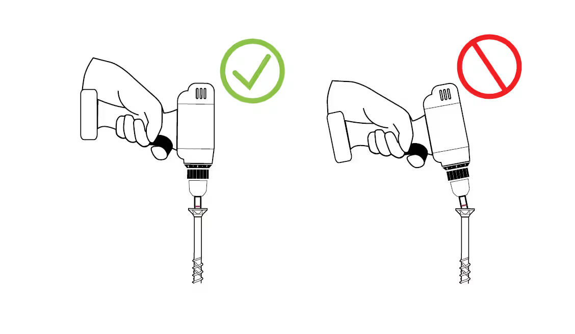
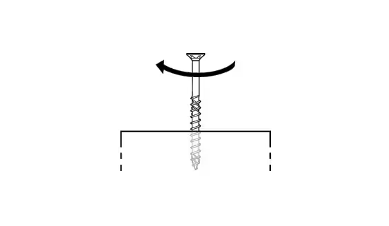
Align the driver bit axis parallel to the fastener axis during installation to allow proper torque transmission and to avoid stripping.

Screw Installation - Decrease RPM

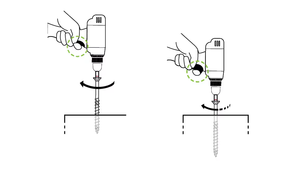
To avoid overtorquing the screw, decrease the rotation speed about 13 mm [ 1/2 in. ] away from the final installed position. This is crucial to prevent wood crushing due to overtorquing, which can impact beam hanger tolerances, potentially impeding overall connection assembly. This is especially important when using an impact drill.

Screw Installation - Drill Pressure

Do not apply excessive pressure on the drill while driving the fastener to prevent fastener buckling or deviation during installation. Only apply the required force or use the recommended holder case to eliminate cam-out effects.

Screw Installation - One-Step Process

To avoid increased torque peaks caused by stopping and restarting the drive-in process, install the screw in one run until the head is lightly seated against the side member. If necessary, a torque wrench may be used to complete installation immediately after the screw has been driven.

Screw Installation - Structural Screws

Install the structural screws from the top down, beginning with the horizontal screws. In the primary member, install the 5/16″ × 4-3/4″ [ 8 × 120 mm ] MTC-FTC horizontal screws for Package A or 5/16″ × 6-1/4″ [ 8 × 160 mm ] MTC-FTC horizontal screws for Package B (Refer to Table 1.1 on Page 20 of Beam Hanger Design Guide ). In the secondary member, install the 5/16″ × 6-1/4″ [ 8 × 160 mm ] MTC-FTC horizontal screws. Once all horizontal screws are installed, install the 5/16″ × 6-1/4″ [ 8 × 160 mm ] MTC-FTC screws in all inclined holes, again working from the top down.

Optional Measures - Pre-Install Wood Plug

Where connectors are housed in the secondary beam, it is recommended to seal the void in the routing below the connector for aesthetics and fire protection. The RIDGE system is equipped with 7/32 in. [ 5.5mm ] diameter diagonal holes so that a wood plug may be pre-installed on the non-routed member in the shop or on site before the secondary beam is lifted into place. The wood plug can be installed with #10 wood screws that are 1-1/2 to 2 in. [ 38 to 51 mm ] long.

Installation Instructions Overall

Refer to the General Notes to Installer in the Beam Hanger Design Guide for further information.

Technical Blogs

Sign Up

Register for a Technical Learning Session

NEWS LETTER

Sign up for MTC Newsletter and keep up to date with all our progress.